First time posting here, I’m based in rural Queensland Australia, on the journey of making our family home smart. Always been fascinated with IC’s as a kid but a few years ago I learned to code in a few web-based languages and looked at combining my skill’s with problem-solving on my small rural property. There are some base things I am automating atm, like climate sensors, tank level sensor, grey water sensor and irrigation system, a couple of touch light switches with motion detection.
Atm as far as lights go I am just doing some trialling, I am building the PSU, MCU, relay, wireless module all into the light switch, this is not the long term plan though. Next year we are renovating and replacing the roof as well as all the wiring (house is about 60 years old). I will locate the relays and their controller with the circuit breakers and split it up as the house will be extended to 21m and I would rather not be running wires the full length of the house.
The Question:
The cabling to the light switch will be a maximum 15m in some area’s and as my light switch will be based on my current capacitive design I will have an MCU (probably a Nano) on the back to detect the touch and send it to the closest switch/relay hub. initially, I was just thinking of an on/off signal but this would be limited by the number of wires in the cabling, so then I looked at creating a serial connection something link RS232 or RS485, but this then makes sending power down the line for the nano a little impractical (and expensive).
I am now toying with the idea of using an ethernet shield and a PoE, I will just have to have a splitter to get it to 5v and break out the data. This is still kind of cheap (each switch costing 15-20AUD) and by running Cat6 everywhere will allow flexibility in the future (like adding more touch switches etc). I will be running Cat6 to every room anyway and will have it also in the ceiling of each room for a sensor hub (temp/humid/gas/fire/motion/light).
There is also another option, to run the switch cable to the room sensor hub (that will anyway have a network connection) with an I2C bus, as it is very unlikely that more than 10 button presses will be happening per second. and the cable will not be longer 3m.
Wiring Cat6 (or even 5e) to each location is a very good idea even if you decide not to go with Ethernet. It gives you a lot of flexibility. That’s exactly what I did, first using it for Ethernet then for switches.
The first part of this episode goes through the history of my light switches, and why I eventually moved away from Ethernet / PoE:
Their current status is what’s shown in episodes 25 and 26, at least for the switches that are installed in my house and in active daily use.
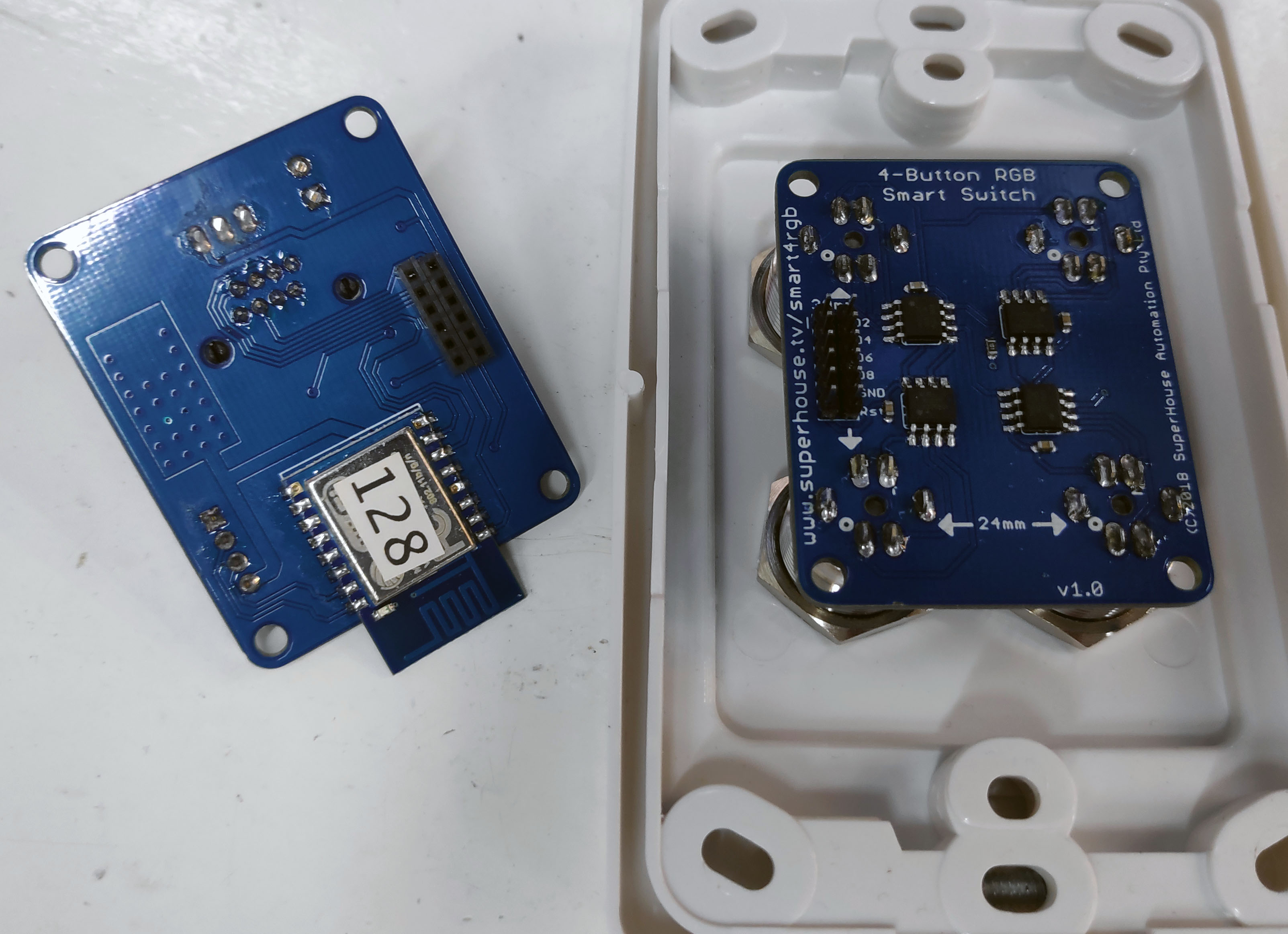
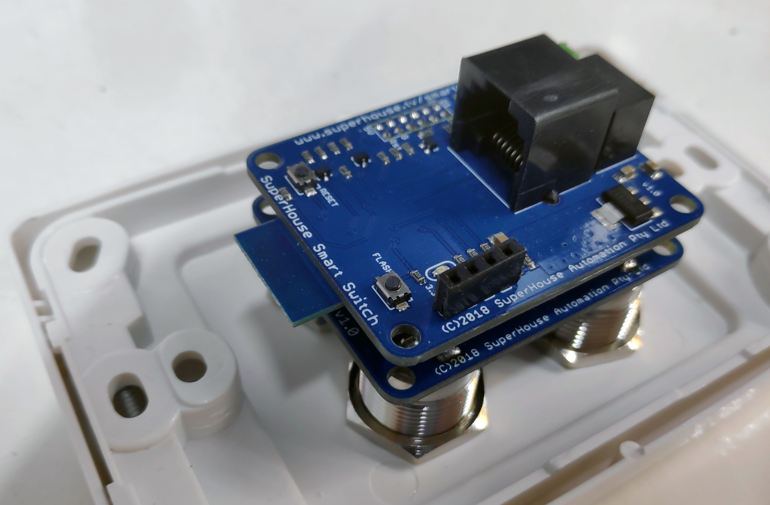
I’ve also designed a more elaborate switch as a drop-in replacement that includes an ESP8266 and uses RGB buttons, so you can simply dial up a colour to customise your switches, or have them change colour to indicate state.
The Smart Switch is for a future video though. It’s at late prototype stage, but I still need to spend some more time cleaning it up. Those videos above are from 2017! I’m so slack.
Since then I’ve done PCBs for both the button carrier and the “smart” part:
Wow that’s an awesome idea, Its also makes sense using the ESP as a cosmetic apparatus and still run the main switching through over Ethernet.
After watching a few more of your videos last night I think I will go with using the Cat6 as a switching mechanism and if i ever want to send data I still have the line.
I like your switching setup and I might as well use your components rather than reinvent the wheel. For my touch capacitive switch, I will use the nano to control the grounding with a mosfet or whatever device that is cheap, less to go wrong and easy upgrade later on.
Atm, I have a esp8266 updating MQTT the action but the nano makes the relay switch so that if wifi cuts out it still works, we have the wifi on a schedule anyway as my daughter doesn’t sleep for some reason when its on. but this is only temporary till the rewiring of the house.
Hi…I would recommend you hire a qualified electrician. Why? Because the photograph you posted (wire.jpg) shows that you are well outside your comfort zone of experience. That exposed, bare copper wire at the relay terminal blocks is lethal.
All of those parts and wire must be contained within an enclosure that is safe from inserted fingers and other foreign objects. You’re risking bodily harm and fire working with household mains.
If someone needs to explain to you how to wire a switch in series with a switch, you absolutely don’t have the skill necessary to complete such a task safely.
Yeah, I was wondering the same thing, what (wire.jpg)? Given the tone of RochLevoff statement, he strikes me as a person who is very impressed with himself and likes to point out others inadequacies as a way of highlighting his obvious brilliance. As it stands, I think he pointed out his own inadequacies.
I doubt there are many makers, delving into DIY smart home wiring, that don’t know enough to enclose mains voltage wiring to avoid electrification of one’s self. Always keep the stuff that will kill yah (110-220V) separated from the friendly (low voltage) stuff is what I say. If nothing else, the Darwin Principle usually weeds out the stupid.
Hi, DavidRK, just remember that cat6 or even 5e is cheap so run at least 2 cables to each switch outlet, even if 1 will do. You might want to upgrade later and add a touch screen controller or who knows what, later. Check out this link for more ideas from my build.