Light Switches - How Jon does it

I wanted to do a quick write up on the overall architecture of Jon’s light switches. The question comes up often enough that I thought I would consolidate the options and layout into one place. There are a few videos on this spanning many years, and the project has evolved over time. I’ll let @jon yell at me in the comments for things I’m missing or get wrong. This will focus mostly on the hardware. Software is a much larger topic, but this will get things set up.

See also:
Superhouse #24: Home Automation System Architecture
SuperHouse #25: Arduino home automation light switch controller
SuperHouse #26: Make your own home automation light switches!
Forum post showing some (future state) RGB LED switches w/ ESP8266

High-level:
The system consists of two independent systems - Inputs and Outputs.

The inputs are the switches on the walls. The outputs are mains-rated relays located in an enclosure with home-run mains wiring for every ceiling light (and some others). Other outputs are mains plugs along the wall. The inputs and outputs are only tied together via programming and logic (think: Node-Red, OpenHAB, Home Assistant, MQTT messaging…). The buttons just post a message to the logic system; which then has options to turn on or off different outputs. Each side could be installed without the other, if desired.

Planning
Start with a plan; including reverting to standard when selling your home. Start the documentation as you go through this planning. Map your house and count how many of each kind switch you want in each room. Options are single, dual, and 4-button switches.

This type of installation would be best considered for new buildings or to be done during a remodel since it requires hardlines to be pulled through to every light and every wall plate that will be included in the system.

I did a sample layout of my house in Microsoft Paint. It doesn’t need to be too fancy.

I created a calculator to add up the cost of the inputs and outputs here Please don’t mess it up :slight_smile: It isn’t protected. Just fill out the four yellow cells and you can leave the rest as default. It will add up what you need to order.

Inputs side

How the switches work
These are nothing more than a button at the end of a very long wire run. It goes directly into a digital input on a Arduino back in the control box/base station. The single, Dual, and Quad button modules can be switched out later without any additional wiring. This requires RJ45 / Cat5/6 cable to be run from each wall plate back to the base station located in a networking closet. There are a few components in that chain which we’ll talk about later, but electrically they are just momentary buttons at the end of long wires.


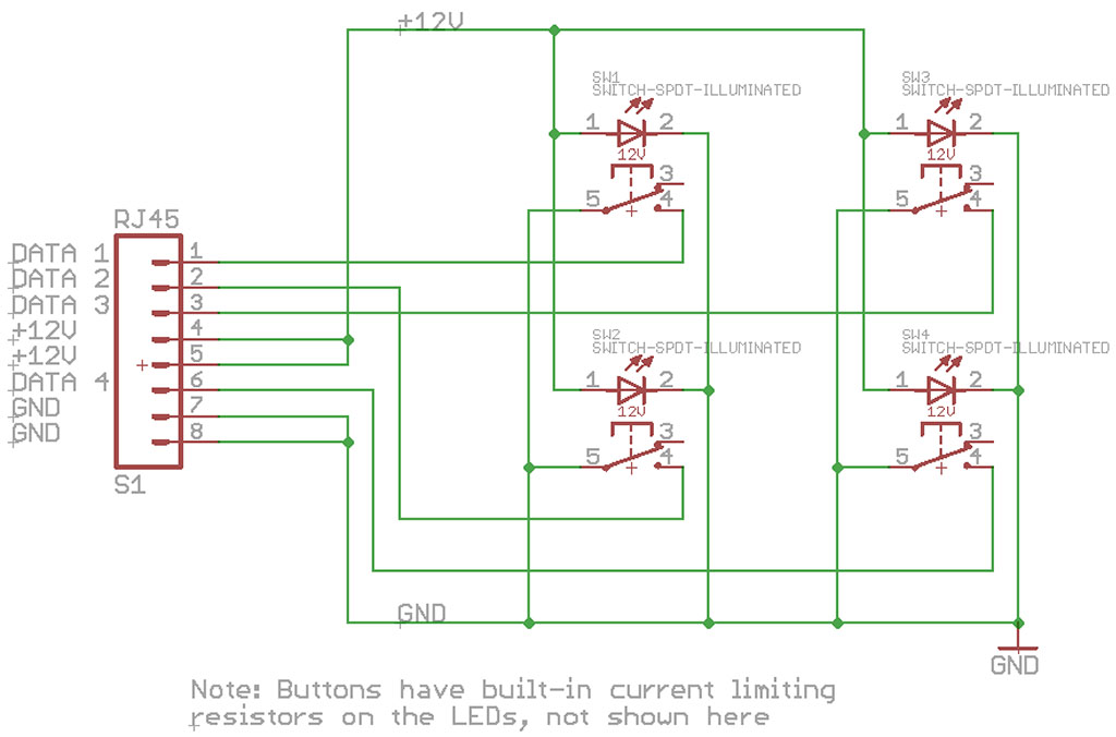
Image from Episode #25

You select how many buttons you need and pick up the PCBs and buttons from HERE

You’ll pick up some wall plate blanks at your hardware store and cut out the 16mm holes for the buttons. Mount the buttons to the wall plate and solder the other end into the PCB and that is done. Plug in the RJ45 and mount in the wall. That part is done.

Reading the buttons
On the other end of the RJ45 cable, we need to wire each signal into a microcontroller. There are a few ways to do this. Jon has made it simple using standard connectorized jacks and a variety of shields. His current iteration uses a RaspberryPi (I believe) as the microcontroller; but the website is currently offering the Arduino styles.

Simple version
The simple option is a basic Arduino Uno style shield HERE which works with up to two wall plates. Note that from here on, I will refer to the wall plate as a unit. It won’t matter if there is one button or four since they are using the standard connectors. So you would be able to write code on a single Uno for two wall plates (between 1 and 8 buttons).

Advanced version
The more advanced version uses a breakout block to split the Ethernet jacks into IDC headers which run over to an Arduino Mega shield. This has four components:

IO Breakout to RJ45
Takes the RJ45 from four wall plates and converts to 2x IDC (“Standard”) pin headers.
IDC cable
Sold in 3 lengths (or you could make your own). Connects the breakout above to the shield.
IO Breakout Shield for Arduino Mega
Fits on standard Mega, but consider the EtherMega since that has onboard Ethernet and supports PoE. Has enough inputs for 16 wall switches.
EtherMega
The EtherMega is not required; you could use a normal Arduino Mega, but this adds the functionality of onboard Ethernet with PoE

There is also THIS option for using an Uno with up to six wall plates. Again; consider the EtherTen with onboard ethernet.

So that gets the buttons back into a microcontroller. You would have to write code to poll the inputs of fire interrupts on each press, then most likely push that over to a rules engine like Node-Red, OpenHAB, HomeAssistant, etc.I would probably suggest using the EtherMega with the Ethernet library and MQTT library installed. Mqtt.Publish(“LightSwitches/plate4/button2/”, “ON”) or something like that.

There are a lot of different ways to plan this out and expand it over time, but this is a good base of where to start.

That is a summary of how the light switch (input) side works. I’ll do another write-up on the outputs side for mains switching.

2 Likes

For EtherMega - do I need extra POE module to supply power to arduino or is it actually built in?

The EtherMega can be powered in one of five ways.

  1. USB cable (just like standard Arduino; this is the most common in testing & debug phases)
  2. 2.1mm Barrel Jack (just like standard Arduino; probably second most common)
  3. VIN pin (just like standard Arduino)
  4. PoE Ad-Hoc (~6-12ish volts; like when running this POE Injector)
  5. Legitimate Poe 802.3af (48V with a specialilzed PoE injector; requires handshaking between the board and the PoE injector. Requires adding-on this module; or similar.)

Think of the EtherMega as nothing more than a normal Arduino Mega combined with an Ethernet shield in one. If you are running a host application on a PC using the serial port (over the USB connector) then you wouldn’t really need the EtherMega.

Hope that helps answer the question.

1 Like

Hi James, It really helps, thank you! I should have posted more details about why I am asking. In Jon’s video - he just plugged in LAN cable into his Arduino and didn’t say what kind of POE injector sits behind, probably the one built by Superhouse. Then he connected jumpers on Mega and that’s it. So I thought maybe some kind of POE regulator is built in to Mega and it wasn’t worth installing POE module, now I understand the difference. I used that module from the beginning with my UniFi POE (802.3af), just wanted to verify it was right.

No problem. You can do whichever option works for you.

Hi @aspork42 - this is a fantastic writeup - thanks for doing it! Did you ever get around to doing the second part, for the outputs/mains switching?

Does anyone have any idea if/when Jon will be making his updated version of the switch modules (with WiFi modules) available?

For context - I am in the planning stages of a new build and want to centralise my lighting control. I am using Z-Wave + openHAB in my current house and it works pretty well, but I really like the idea of Jon’s approach - much more flexible and easier to change. But I am struggling to find quality componentry to ensure it is a bullet proof solution.

Jon’s store is great but there seems to be limited stock and I can’t seem to source an EtherMega from anywhere. Just worried if I build this thing and something needs replacing, I am going to be stuck.

Hello!
I don’t think I ever did do a write up. I should get to that… the short story is that the output controller is just flipping relays on and off with each room in the house having its own lighting circuit running back to the ‘main panel’. You can use the same Arduino for inputs as you do for outputs, but it is likely easier to use a different one. You can use something like a relay shield from his store to trigger the lighting relays.

check out this other post (video linked) to get an idea of the layout:

Also @jon could also help out with stocking of items. The wifi wall button panel isn’t commercially available yet. We could hit him up for more stock of EtherMega though.

I am pretty happy with the overall design - and I agree that separating out the input/output controllers is sensible - especially if you want to introduce automation logic in between them (which I do, via openHAB).

TBH I am not that interested in the WiFi aspect of Jon’s new switch design - so I guess I could just use his v1 designs - I was wondering if there had been other improvements in the new design how, aside from WiFi?

The big question I have is what to use for the 240VAC relays - I found this via another post in these forums and have made enquiries but I noticed it has no certification so my sparky is very unlikely to be happy - even though they seem perfect for the job.

I would love to know what Jon, or others who have built this kind of system, ended up using for the distribution board relays, and how they interfaced those with their Arduino or output controller.

Any tips or suggestions would be great!

Many thanks,
Ben

The other thing I would love to get my hands on the latest light switch controller Jon shows here at around the 15 min mark.

This is so elegant and compact and simplifies the whole thing. I couldn’t find it on the store however so I presume it hasn’t been made commercially available yet?

Ummm… well, there is this version available I/O Breakout To RJ45 – SuperHouse Automation which is a 4-channel version instead of the Super Jumbo he shows. These are just really long extension cables for the pushbuttons.

1 Like

Here are some relays which may work. These are generally industrial quality. Most often they use a 24V DC signal to control the relay. https://www.newark.com/w/c/switches-relays/relays/power-relays?relay-mounting=din-rail|din-rail-panel&contact-voltage-vac=220v|220vac|230v|230vac|240v|240vac

This is a relay driver shield that you could put on the Arduino to run each relay. 8-Channel Relay Driver Shield – SuperHouse Automation
Check out the description on that product page.

1 Like

Oh! I tagged @jon that post, and like magic, he listed more EtherMegas on the website. You can purchase them now!

1 Like

Ha - good work! Thanks for those links also, very helpful.

I would love to get my hands on his latest controller tho, the one that uses I2C so you only need a standard Arduino to address each port. Seems like a very elegant solution.

I realise it is still in prototype phase however, so I might be dreaming, but I have about a year before I will need them, the house build won’t be starting for another 6 months and will take a while.