Sweet, sweet success 
I can’t do anything more on this for a few days (Easter getting in the way) but hopefully I’ll get a chance to figure out how much these will cost. They’re very simple but the bare PCB cost a few bucks just because it’s so big.
Sweet, sweet success
I can’t do anything more on this for a few days (Easter getting in the way) but hopefully I’ll get a chance to figure out how much these will cost. They’re very simple but the bare PCB cost a few bucks just because it’s so big.
I’ve started making a page for this, but I haven’t done proper photos yet so I’ll update it later. Better to have something up though
and ordered.
Thanks for your help with this Jon.
Hi Jon,
I don’t have a 3D printer (yet), and was wondering if you could make me some DIN rail mounts for that PCB? If not I can make do.
And shipped
Sure, I’ll work on a design for a DIN rail mount and send you some (there are 3 positions for mounting holes on the PCB) but I haven’t done it yet. Hopefully in the next day or so I’ll get it designed.
Hi everyone,
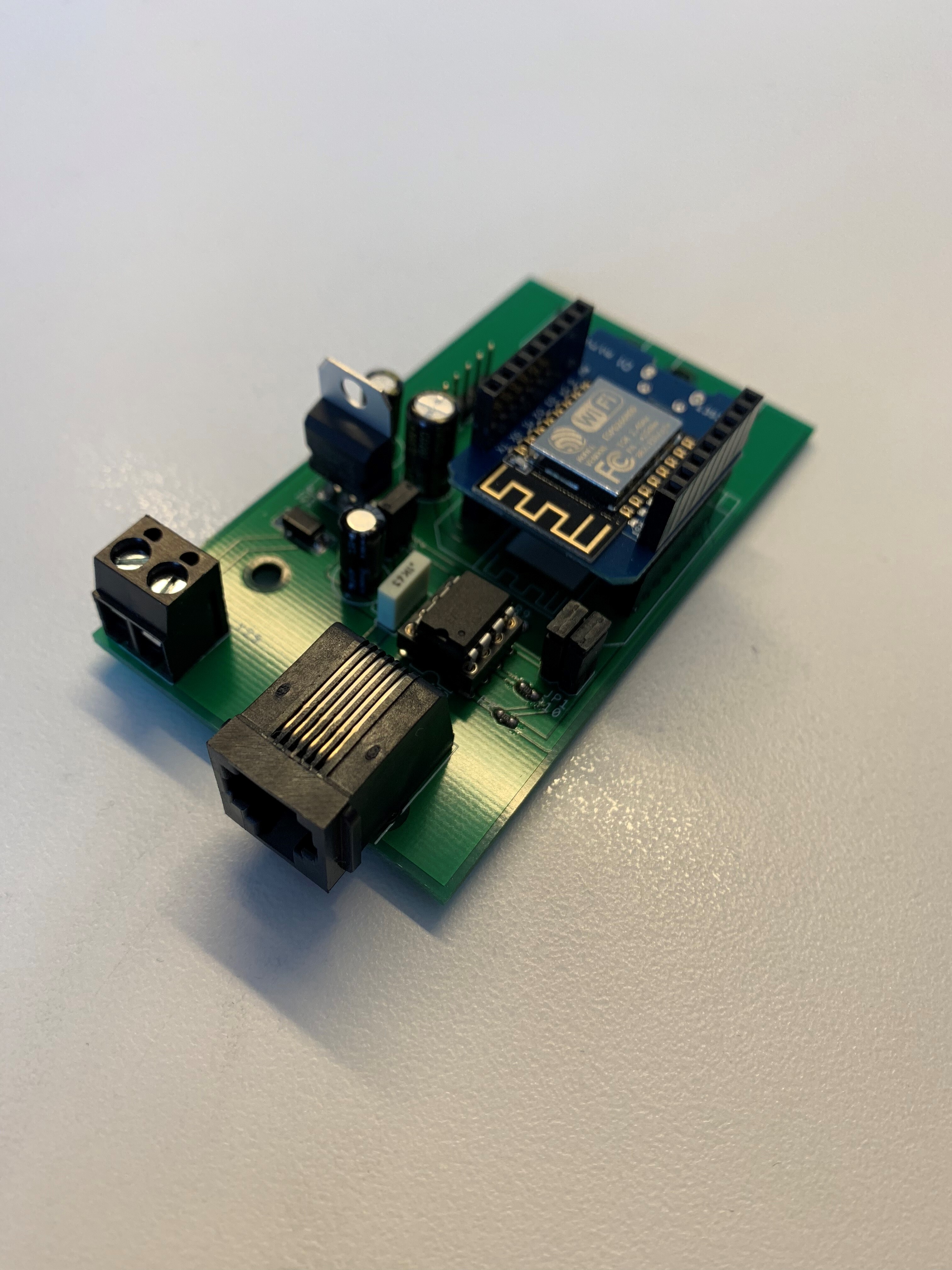
I decided to do this because I read this thread. I created a DIN Rail Relay driver with 9x 16A Relays and a LIN Interface. I’d love to get your thoughts? I’m kinda new to all this and only started developing circuits in November, but I have tried as hard as possible to learn as much as I can. I’ve linked it below to my website.
Thanks.
Josh
That looks really cool, Josh! Nice work.
Do you have a setup guide or any info about how you communicate with it? I like the use of LINbus for this sort of project. I’ve been doing a lot of work with CAN recently which is a good option too. I’d like to see more people designing devices the way you have, with a standard interface so they can work together.
Hi Jon, thanks for your reply!
I’m working on a full ‘User Guide’ type of document, but essentially you set the address using the pin headers, in the same way as the Relay 8 Shields, with the default being Address 1 (the idea is the LIN Bus master is address 0). Then each relay is given a number, with the first being 1, then 2 etc. Finally the state is set as 1 or 0, and you send this over the LIN in the format “ARD:RELAY:STATE” so to turn the first relay of unit 1 on would be “1:1:1”. There is a ATMega328P inside that uses simple Serial.parseInt to read the data.
I just got what you see in the picture in yesterday, still trying to get it working. It’s a sort of interface, a bit like how you use the EtherMega to inferface with your switchboard, except this is simply a D1 Mini with a LIN Interface and a voltage regulator. I am also working on an Ethernet POE version.
I also got myself the same reflow-oven you have to put together my projects, a great find I must say!!
I’m going to add some pictures of the inside of the relay module to the link I posted in a bit.
Thanks again,
Josh
Looks like you’re on a roll
I see you’re selling these modules on your site. Do you have any plans for releasing them under an open licence so others can see how they work?
Hi Jon,
Yes I am planning on, could you perhaps recommend one? Which one do you use?
Also, just something I have been wondering, what is the name of your laser cutter? I’ve been looking to outfit my home workshop/maker area/massive mess with one but haven’t been able to find any good models. Thanks. Josh
Josh
I believe Jon puts his stuff under GPL-2.0 which allows people to use the source code, which he posts on a GIT repository, and the same with his board designs which he offers the Gerber files for if people want to print some and populate them on their own. There is really only 2 Open license types that apply to this kind of thing (as I understand it). GPL-2.0 and GPL-3.0. The definitions for these two are at the OPEN SOURCE INITIATIVE pages…
Open licensing allows others access to the inner workings of the product and depending on the license type, the freedom to use that software and design with or without modifications. Some will use it as a building block for their own designs and will customize it for their own needs. Some will just want to know what is in the magic black box and have you create one for them. The beauty of the maker community is that we share a lot of what we build so that others can add on to the design and refine it. Open licensing also gives us as makers a third party look at our products and often that leads to people offering direction on how to make it better. I love the maker community!!!
As Guru said, I use typically GPL for source code that I write myself. For code that I’ve derived from someone else’s work, I honour whatever license they specified, which is mostly GPL but you sometimes see BSD or other licenses too.
For hardware designs the situation is a bit more complicated because it doesn’t quite fall under the same legal framework as text or artwork. The basis of the GPL is copyright, so it uses the rights given to the creator as the copyright holder to allow them to use those rights to dictate how the work should be shared. It blew my mind when I first figured out that Open licenses actually require copyright (which is designed to limit what can be done with a work) for the license to work properly and enforce that the work can be shared. It’s a clever legal hack.
But things like CAD files (board designs) aren’t classified as “art” or “creative works” legally, so applying the GPL to a hardware design is very shaky. It probably wouldn’t be enforceable in court. To solve that problem there are licenses such as the TAPR Open Hardware License (which I normally use) that were specifically written to have the same intended outcome as the GPL, but to base their mechanism in different legal terms that apply more to hardware. So you can think of the TAPR OHL as being like the GPL, but for hardware.
These days you mostly see the CERN Open Hardware License being used, which is mostly just the TAPR OHL with the name replaced. When CERN started doing a lot of Open Hardware work they needed a license so they used the TAPR OHL, and put their own name on it. Now many people seem to think they invented it, when all they really did was popularise it!
My laser cutter is a Redsail 40W laser engraver that I bought very cheaply from a friend who had a sign writing business. They imported a few of them and then didn’t use them, so I bought one second-hand but unused. Mine is many years old and the controller was absolutely rubbish, so I paid a friend who knew a lot about laser cutters to strip out all the wiring and start from scratch with a new controller.
Newer cutters are probably much better than mine, with more modern controllers, so I wouldn’t use mine as an example of what’s worth getting.
Watched the YouTube video of your prototype in action a couple of months ago and commented regarding the possibility of a 16 channel relay shield. Then found this discussion and realised you’d already had that thought… Knew you would’ve 
I’m currently thinking I want 64 relays but having 8 x 8 sheilds plus the Uno is one heck of a sandwich!
So I’d really be interested if you utilised all 16 channels on the chip and added 8 more screw terminals to a sheild or separate board as you mentioned.
Would it be possible to expand the current 8 layout and have 8 more screw terminals on the other side? I could probably handle having 4 stacked on top of the Uno although side by side might still be the better way to go.
Andy
Hi Andy! Sorry about the super slow reply. There have been a few issues in my life recently 
Yes, only using 8 of the 16 GPIOs on the driver chip has always bugged me. It seems like such a waste. In fact a few years ago I did a rough layout of a 16 channel version of this shield, but it ended up HUGE so I never finished it. It would make sense as a board that’s just a rectangular module with I2C interface, but trying to make it work in the shield form factor just looked silly.
While I’ve been absent the last couple of months I’ve been working on several projects that use this same chip on a much bigger scale. Later today I’ll post about an in-progress design for a rack mount light switch controller that uses 6 of the chips (all 16 channels on each) for 96 input lines, plus a 7th chip to drive menu buttons for an LCD.
Once I’m done with that project I might come back to doing an updated output controller. I’ve already built several different types that have never been shown in SuperHouse videos.
Jon, don’t apologise for life being a challenge. Everyone’s priorities have to change sometimes due to circumstance. I think I probably speak for the majority of folks that interact with you in that you owe us nothing. We’re here because we appreciate what you bring to the smart home arena and whilst we look forward to seeing what comes out of your brain next, we have no right to demand anything. Work at whatever pace is best for you and only do it because you want to not because you have to.
The projects you mention sound really interesting. For me personally a shield isn’t that important so a separate board wouldn’t be a problem.
I’ve looked at the Macetech Centipede board but the input/output pin headers aren’t ideal for my needs. I’d prefer screw terminals. I know I could use a breakout with screw terminals but the fewer parts to the overall installation would be better in my opinion if only for the next person that comes along after me and has to figure out what it all does!
I look forward to seeing what you’ve been up to.
Take it easy mate.
I am wanting one for my project at home,
you could make it as a two shield board with an interconnect between boards, meaning you could make it
two boards in a row then a cable between and have more boards somewhere else where they fit, I hope this makes sense, I like that Jon is looking at making a 16 output relay board, something I would love to see is a board for the mega, a 16 input on the analogue for security to allow more sensors with-in the house, I am looking at about 10 - 12 just as a start on my system.
Keep the dream alive, as Jon end line, go build some thing great!
I can’t believe I missed this topic as this is the stage I am into on my own lighting panel. The main lighting, homerun panel is on the wall, the power/ circuit breaker box is mounted with 4 15 amp breakers. I am ready to run all of my cat5 wire to the light switches. The only thing holding me back is the relay control configuration. All of these suggestions look like great candidates for my control box. I want to mount my relay circuit boards on din rails so they are easy to access and easy to place.
I also want to communicate using an eithernet connection as I don’t like wi-fi for infrastructure. All of my lighting control is in the main panel but I was thinking of putting the shop lighting and the basement on separate homerun lighting panels, just to make the wiring distances less to the panel. I still want all of the main control “brains” in the attic in one central location. A simple buss system seems like the way to go if it is easy to control using one of the home control schemes like Openhouse, MQTT or whatever. I will watch this thread with anticipation as I am ready to get this part of the project behind me. Also it would be nice to finally have some descent lighting.
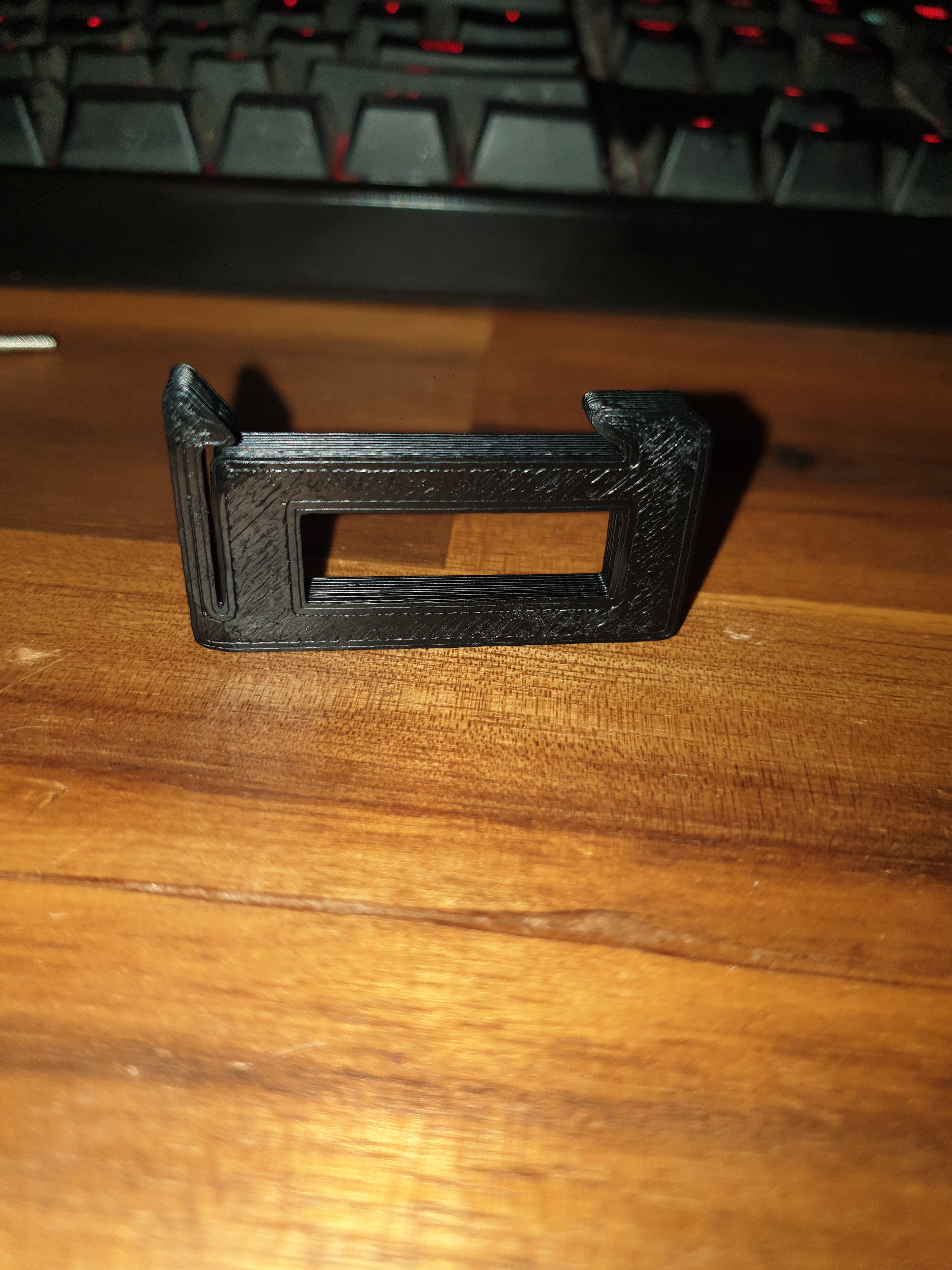
Here is my first test print for the DIN Mount bracket for the relay carrier board, the spacing for everything seams fine, just waiting on the next print to finish this one is a bit to thin,
will report back once its done in about 30mins
EDIT
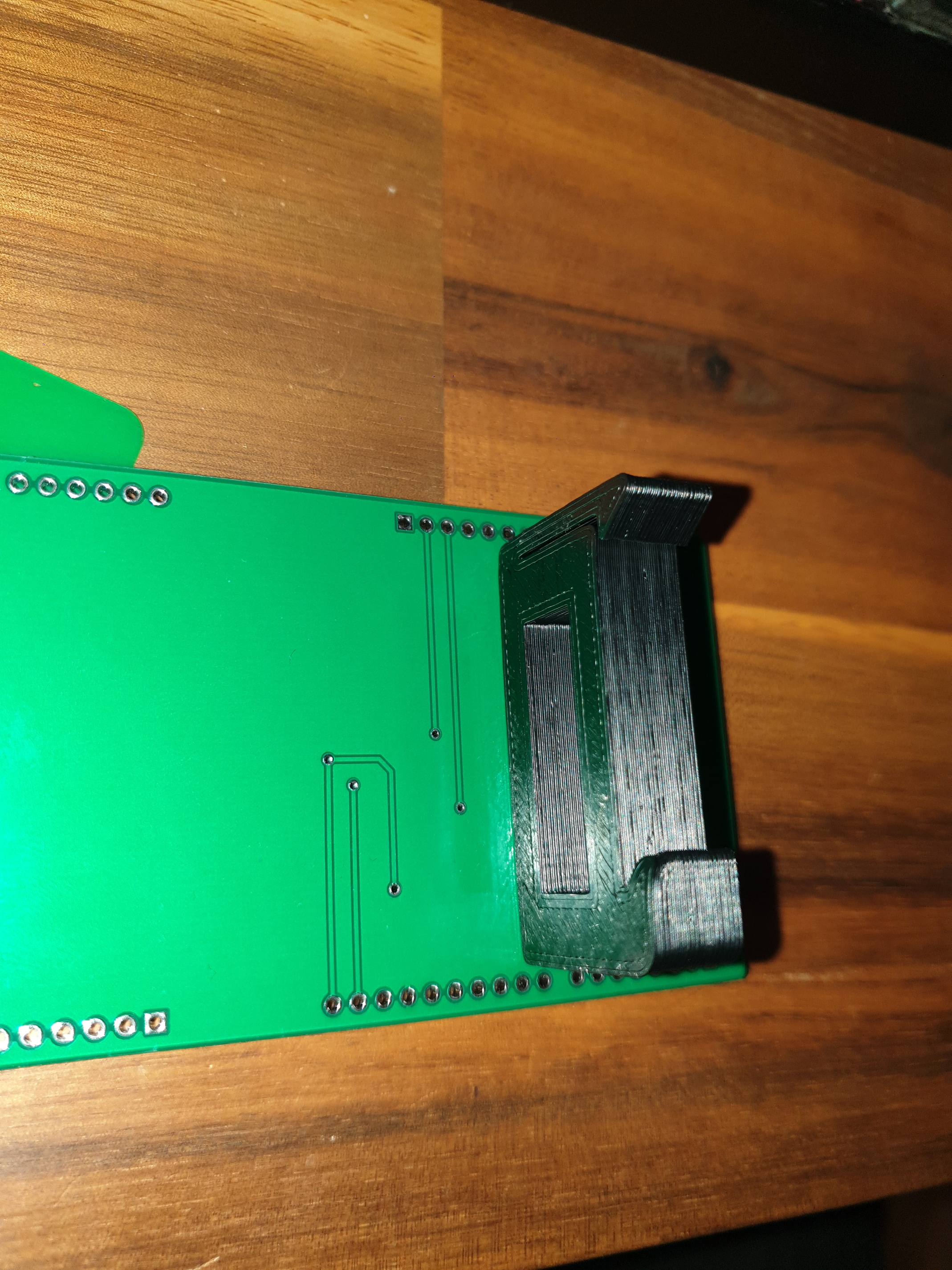
Updated version has finished. works much better. this design fits within
See the second Photo.
i currently have a bunch of these printing if anyone wants any ill chuck up a store page or something and sell them in sets of 3 for a few bucks. otherwise ill post the design files for those who wants to print their own
Have a read of these 2 topics, might be able to help you with your home automation project
Hi @Bedrock,
Great work! It would be great if you could share the design for the DIN mount for those of us that have 3d printers.