I am in the process of deciding how to mount all my gear into a dedicated ELV switchboard and am finding that stacking Arduino shields is a little awkward when you have more than a few. I am intending on connecting four relay8 boards to an ethernet connected Arduino and would like to mount them side by side rather than stacking. These particular shields communicate via the I2C bus so it would be possible to jumper them, but in my ideal world I would use a PCB that I could push the shields onto and that would connect to an Arduino.
Before I go ahead and make a custom PCB, I thought I would ask if anyone could offer some suggestions.
That is an interesting idea. I had not put much thought into side by side mounting shields but that makes all sorts of sense. Would make wiring a lot easier than if they were stacked, as well as troubleshooting if there was an issue. Outside of printing a custom board though, you’d be looking at making some super clunky cables. Probably not the idea situation either.
Yes, it’s a very interesting idea! It would be easy to make a carrier board that they can plug into. In fact this is so interesting that I’ll do it for you, because I think others would be interested as well. The way you’ve laid out the shields makes sense for the Relay8s.
Relative to those shields, where do you think the Arduino should be? I can think of 2 good ways to do this:
Make a carrier that mounts those 4 shields, with external connections for power and I2C. Then the Arduino could be physically mounted separately, which would give you lots of flexibility. It would also mean that the carriers could be daisy-chained.
Put a mounting location for an Arduino at one end of the row of shields. It would probably be upside-down, so that it would plug in on top of the carrier board instead of mounting underneath it. That would make it have the same clearance as the shields, and let the carrier board be the mechanical mount for everything.
Ultimately the method that maximises flexibility would make the most sense to the most number of people.
Part of the attraction for mounting the shields side by side is ease of accessing the screw terminals, but I am also trying to overcome height limits of my cabinet. I can easily fit four relay8s as shown with some room to spare for an Arduino (that would be my preference), but others may have different space limitations and that may be too long. It may also be something that could be offered in a 2+Arduino form factor for those that have space limitations.
With such a long board, the method of mounting would also need to support the PCB to avoid flex while pushing down causing a sort. What do you think the best way to mount the carrier board would be?
I was thinking of putting holes at multiple points along the carrier so that it could either be screwed onto standoffs, or attached to DIN rail clips. I did the basic board layout earlier today so I’ll post a screenshot when I’m back on my computer.
There are 3 things I’m undecided about with this board, so I’d appreciate suggestions.
Connections. I put simple 1x6 headers on each end so they can be chained together or connected to an Arduino from either end, but I don’t like the simple header because it’ll mean using jumper wires to connect to different parts of the Arduino header. I’ve wondered about putting on perhaps a 2x6 header in the same format that I use for I/O Breakout boards, so they could be connected and chained using IDC cables:
So I’d like to know how you want to connect it to an Arduino.
Physical mounting. I haven’t added holes yet. I figured that I’d add mounting holes so that it could be either screwed to a base, or attached to mounts such as DIN rail clips that could be 3D printed.
Enclosure. I like designing boards to fit into off-the-shelf enclosures so that they can be fitted easily and give a professional result, but I don’t know of any cases that would be the right dimensions for this.
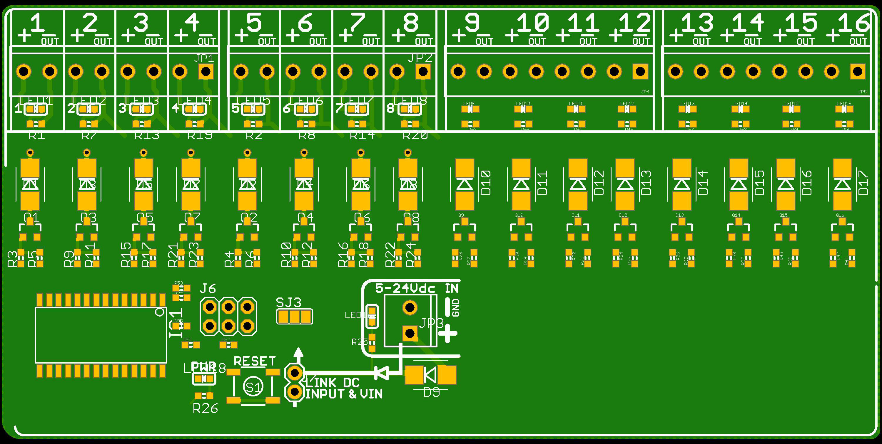
But doing all this has made me think about a totally different solution to the problem. The I2C latch chip on the Relay8 shields actually has 16 outputs (2 banks of 8) but I limited it to 8 outputs on the shield just because it wasn’t practical to fit more screw connectors on the edge. So as a different approach, what I could do is design a 16-channel relay driver board based on the same circuit as the Relay8, but in a simple rectangle shape so they can be mounted separately and connected to an Arduino like this carrier instead of being made like a shield. A general purpose I2C relay driver board (not a shield) could actually be a really useful module for various projects.
And since I started thinking down that track, it’s only a small step more to add a microcontroller and power supply, and integrate the Arduino directly into the board, so it would be a rectangular 16-channel relay driver Arduino. Perhaps that’s going too far though, and the 16-channel board with just I2C is a better balance.
I couldn’t help myself, so I put together a rough concept of a 16-channel relay driver module. This isn’t routed yet, it’s just a Relay8 shield that’s been mashed into a different shape and extra terminals added. This would effectively be the same as 2 x Relay8 shields mounted side by side, integrated into a single PCB. I2C could pass-through multiple modules.
The problem is that it wouldn’t provide relay power to the module, so it would be necessary to connect 12V (or whatever your relays require) separately through a screw terminal. Would this be acceptable?
Also, the carrier board version above doesn’t need to be so high. The top could be trimmed down to just above the headers. I made it the height of the Relay8 shield, but there’s no reason for it to be as high as the screw terminals because there’s no mechanical connection above that point anyway.
I have read through this and laughed until my stomach hurt. This is proof that prototyping is a monster! In a fun way of course. You take a simple idea… a way to connect a handful of commercially produced boards… and morph it into the sum of all the boards you were trying to connect, creating an entirely new product. It’s awesome but it illustrates how modular electronics really is and showcases how hard it is to sift through the existing products to find a solution. By the time you do find a solution, chances are, there is already something that does what you wanted to do and better (with more doo-dads that do cool stuff) that you have yet to find. I have yet to come up with a conceptual prototype (for something pretty simple) that didn’t have a commercially produced version for a quarter of what I spent to build my prototype, and it had other options built in that I hadn’t even thought of yet. What a world we are in right now! Your imagination is the limit.
I know, it’s crazy! I spend more timing going through “what if?” options in my head than doing the actual design. I start going down a rabbit hole of “if I add this feature…” ideas, and before I realise it, what I’m thinking about is nothing like the original problem I was trying to solve. Or it solves it in a way that I didn’t think of in the beginning.
Oh, and this rabbit hole keeps getting deeper. Tonight I was worrying that I was starting to over-think it and make a board that’s way too complicated for the original problem, and then I had a brain-wave: what if we went back to the original idea of a breakout for the shields, but I just plonked an ESP8266 on it? It would still be a very simple carrier board for the shields, but with the addition of only a few parts it could become self-contained and even run Tasmota! The MCP23017 is already supported in Tasmota, it just needs an option turned on.
Right now I think the most interesting way to get quickly to a useful end result is to make a simple carrier board like the original idea, with external connections for power and I2C, but also include a footprint so that an ESP-12 module could be installed and do away with the Arduino altogether.
The longer I think about this problem, the more possible solutions I’ll dream up
I quite like all the ideas above. I can see myself using pretty much all of the options listed.
A carrier board with an ESP8266 would be kinda great, except that I much prefer to use ethernet as opposed to a wifi connection. For my purpose, I would want to have an ethernet PHY and a CAN transceiver (this is a longer story for a future post). Is this a possibility?
I like the versatility of the 16 way relay drivers designed for DIN rail or enclosure mount. External power to power the relays via screw terminals is not a problem at all, and the grove connectors look quite neat.
A hybrid of the two would also be to offer a 16 way relay driver board that is compatible with the carrier board, and if it had mounting holes, it could be mounted on a DIN rail, or in an enclosure simply by snipping the arduino mount pins.
I think that regardless of which direction you decide to go, I will happily be your tester.
Awesome, thanks for the feedback! I’m sitting in the airport in Hobart right now about to head home, so I did some cleaning up on the basic carrier board concept. I think the fastest path to a working solution is a basic carrier with a Grove connector and screw terminals for relay power, so I’ll send the files off for fab when I get home. I’ll also continue exploring the other options.
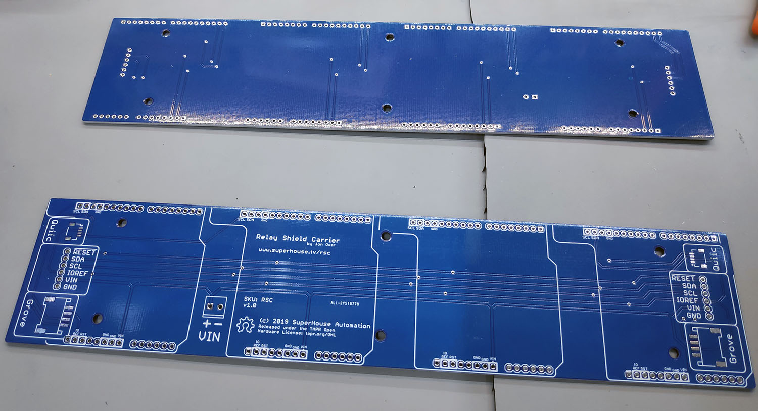
I’ll post a pic of the final carrier board design once I generate the production files.
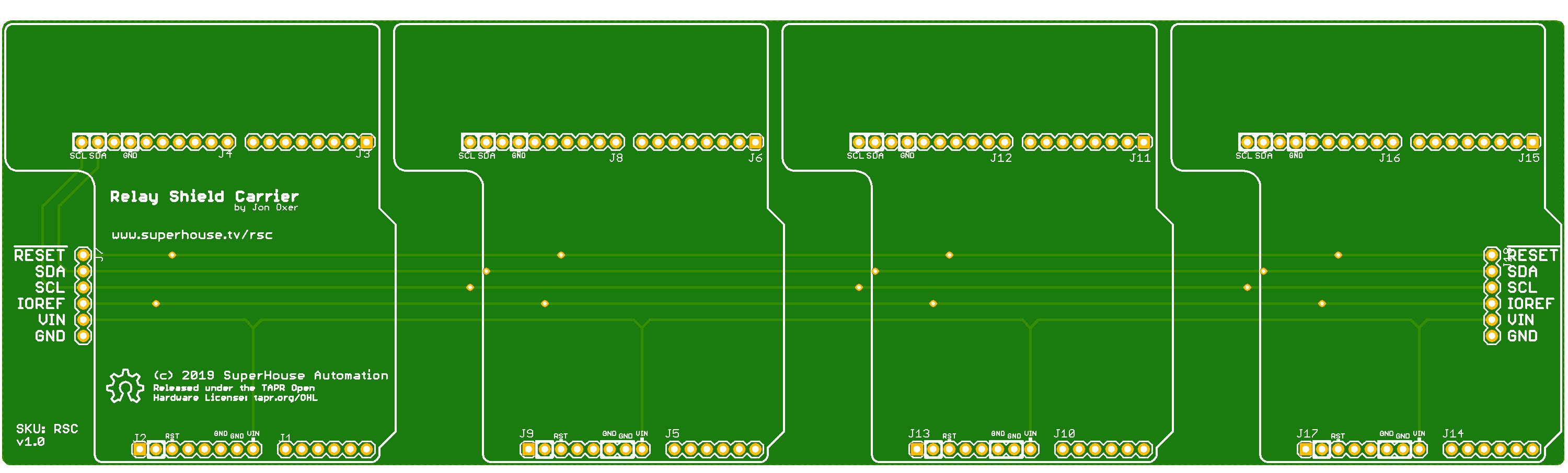
I’ll be sending these off for production in a couple of minutes. Each end has a Grove connector, a Qwiic connector, and regular 0.1" headers so it can be hooked up in whatever way is most convenient.
It also has a 3.5mm screw terminal for VIN, so that relay power can be connected separately when using either Grove or Qwiic.
3.2mm holes are included for 3 mounting clips, so that it can be attached to a DIN rail.
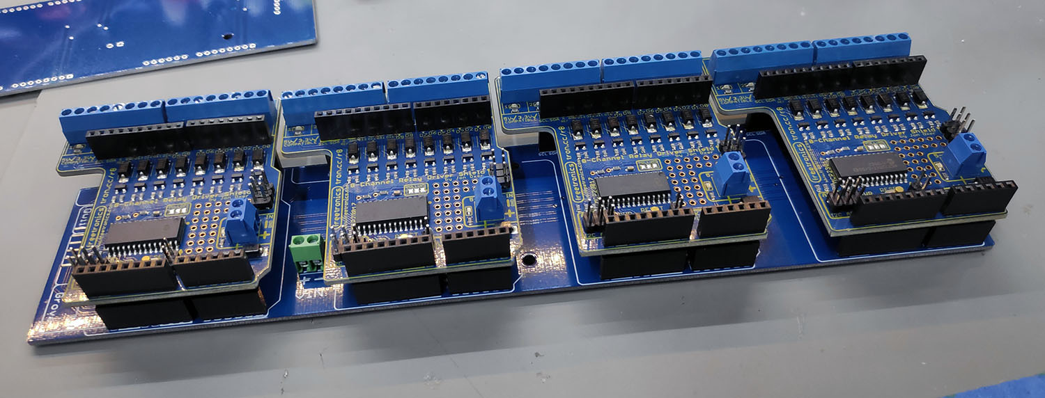
Just delivered by DHL 10 minutes ago! I’m going to put on some headers now, but I’ll be out for most of the day so I won’t have a chance to test them properly until later. I don’t have any Grove or Qwiic connectors (or shields) so I won’t be able to test those, but I can test via the pin headers.