(A lot cheaper as singles and got one even cheaper via “warehouse deal”. The price doesn’t bode well for quality but better finding out after experimenting with a few as opposed to ordering the whole lot)
With tax and a couple misc cables, resistors, etc that I’ll need the total came to about $280 USD. I left off the Pi 3B+ as I’ve got an old Pi 2B I can experiment with and I only got enough speakers and volume controls that I can even verify things actually work. Somebody wrote up their experience dealing with the relay board and posted a manual here that I plan on using.
I’m waiting on shipping now and with any luck it won’t be a couple waste.
My plan once I get everything is to do things incrementally:
Existing known audio source -> Amp -> Speakers
Pi+DAC -> Amp -> Speakers
Pi+DAC -> Amp -> Volume -> Speakers
Pi+DAC -> Amp -> Distribution -> Speakers
Pi+DAC -> Amp -> Distribution -> Volume -> Speakers (and then add more speakers)
Add Relays, Test combinations of “rooms”
Add streaming sources, mobile UI, and voice commands
I haven’t gotten around to fully checking that I’ll be able to combine the Pi, DAC, and relay board all on one Pi but I’ve got a spare Zero W and a Pine64 that I can sub in for experimentation if needed.
I hope to take photos/video as I go and provided there’s something of value (whether success or failure) I plan to upload the experience.
That is good that you found a speaker breakout panel. That will help a lot. And actually with the in-room volume controls you really don’t need the eight relay block at this point. But down the road you might decide to use it between the speaker break out panel and your relay block so that you have a remote way to disconnect each room but I assume that those speaker volume controls actually have a zero point on them meaning that once the volume is turned all the way down it is essentially disconnecting the speakers. Which is exactly what the 8 relay board was going to do. But you are absolutely on the right track and it looks like your incremental roll-out plan for testing is Bulletproof. I say that tongue-in-cheek of course because we all know what happens when you try and plan for every contingency. I excitedly await to see what you have in store for this build.
If I’m understanding that right, doing the relays, means you should be able to add extra audio streams incrementally, by duplicating the dac/amp/relay section, and tying the relay outputs together (with some logic to prevent two streams being dumped onto the same room run, that could get messy).
So then you’d need one dac/amp/relay set per person… about what, $300 per person, rather than $300 per room… This way, you CAN have a speaker in the shower and dunny too…!
Then you just need presence detection so the music follows your phone automagically…
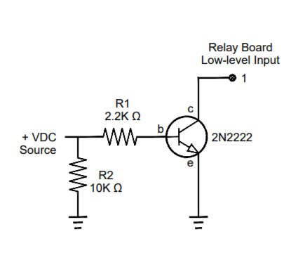
I’m still waiting on the amp so I’ve begun fiddling with the relays. As I understand it from multiple postings I’ve seen on forums and such, it’s best to protect the pi via the following:
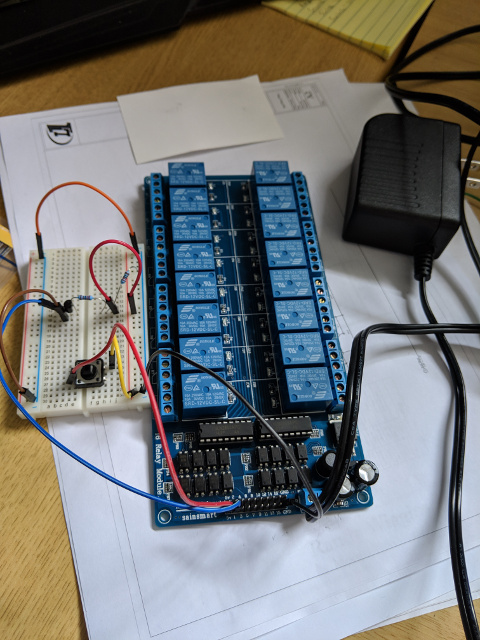
I played with this, and ended up with the following on a breadboard passing through a button (novice setup, I know):
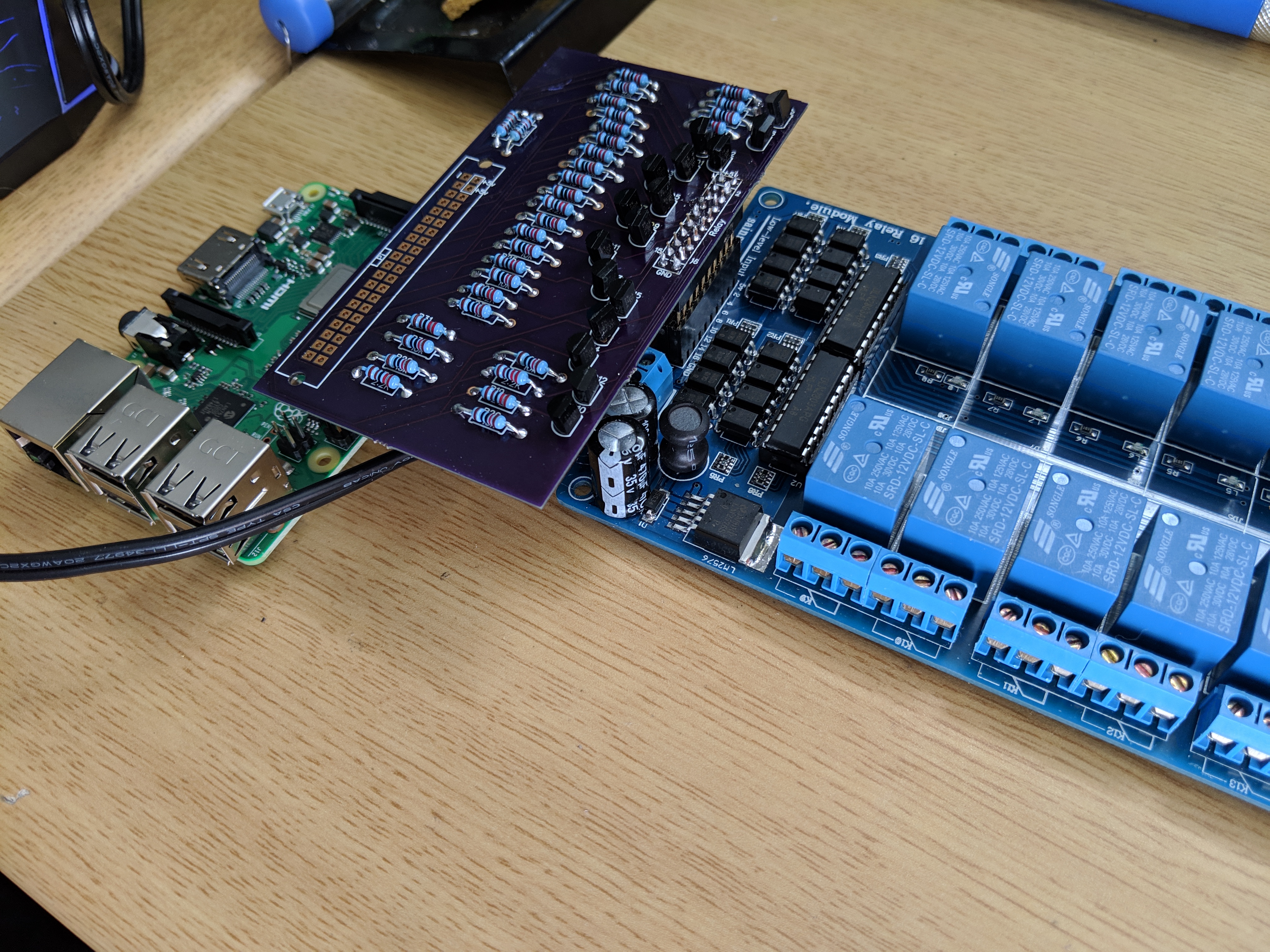
If I hold the button down it does actually flip the relay so that’s good. Next I’ll be wiring it to the Pi and attempting to control the relay from the pi itself. However, when i’m done I’ll be not wanting to use a breadboard so I’m learning and researching into designing a PCB. I have very little idea of what I’m doing but I’m feeling may way through the dark. I have a rough draft but I’m having a friend who is an electrical engineer take a look before I post it so I don’t make a fool of myself or mislead any other novices into using a poor example.
I started playing around a bit on https://easyeda.com. Does anybody have any feedback on that service? Any other suggestions?
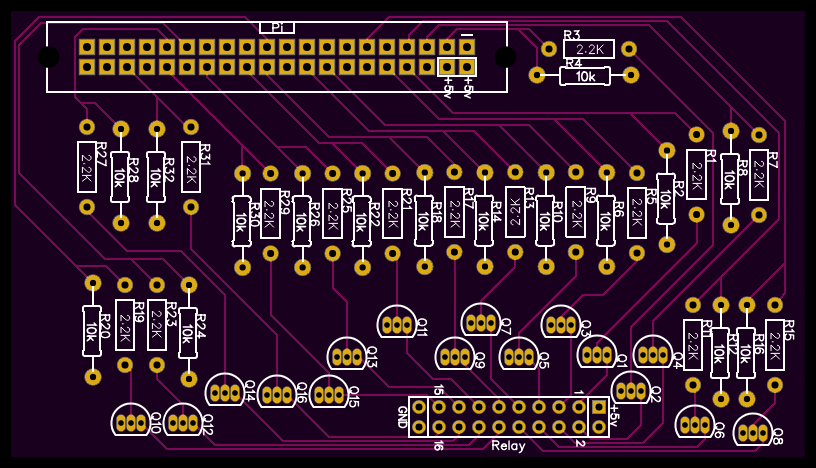
The back side of the board has a solid ground plane and a large +5v track that powers the pi. I mapped the pins so they don’t overlap with my DAC so I should technically be able to run both on the same pi I think. If not I’ll just separate the DAC to a separate pi and the design should still hold.
Good luck - congrats on your first PCB!
Just wondering about the pin header - is this flipped around versus how a normal hat would sit on a regular Pi? To me, this looks like it would have to sit 180 degrees around from how they normally sit. Did you get stacking headers?
It will be flipped. I have it extending to the side of the pi rather than over the top of it. I’m not sure why I made that judgement call but it shouldn’t hurt anything.
As for further update I’ve tested audio output from the DAC and the amp and speakers sound fine. While I’m waiting on my board I’m trying to get the pi working as a media server how I want. I tried Max2play and logitech media server and did not like it - it was very clunky and had the overhead of a local interface where I want a headless server. I’m working with Pi Musicbox now and it seems quite a bit cleaner but I’m still working out how to get it all integrated with voice control and streaming the way I want it.
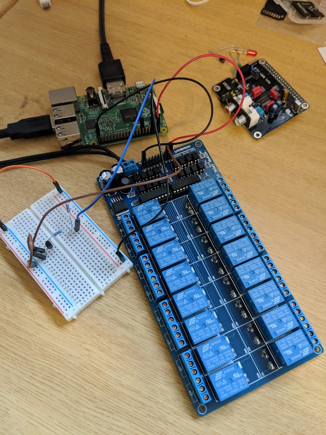
My board is in and with my lack of skills I was, with much difficulty, able to solder it. The transistors were extremely difficult for me (newbie at soldering + familial tremor in hands + very small, close-together pads). I used a multimeter to check my efforts and redid most of the transistors several times. I ran into a problem with my design - I didn’t factor in the capacitor height on the relay board so it doesn’t stack cleanly. I had to add in some stacking headers and that leaves the leads exposed a bit because they are extra tall… not sure if I should trim or what.
Only thing left is to add the headers for the pi and code it up (that last part is my domain).
As for the player, I’ve started from scratch with a plain install of raspbian stretch lite and I added Mopidy. Between support for MPD and UPNP/DLNA it works pretty well. I added HomeAssistant because OpenHab’s MPD support is gone in version 2 and found it a lot easier to work with. I’ve successfully streamed from multiple Windows PCs and multiple phones. I plan on setting up some pre-defined streams and also copying my CD library to a network share and accessing it via SMB.
I’m trying to decide… I’ve actually got it where all this can technically run on a single pi but I may separate and use multiple. If nothing else maybe the HomeAssistant should run separate.
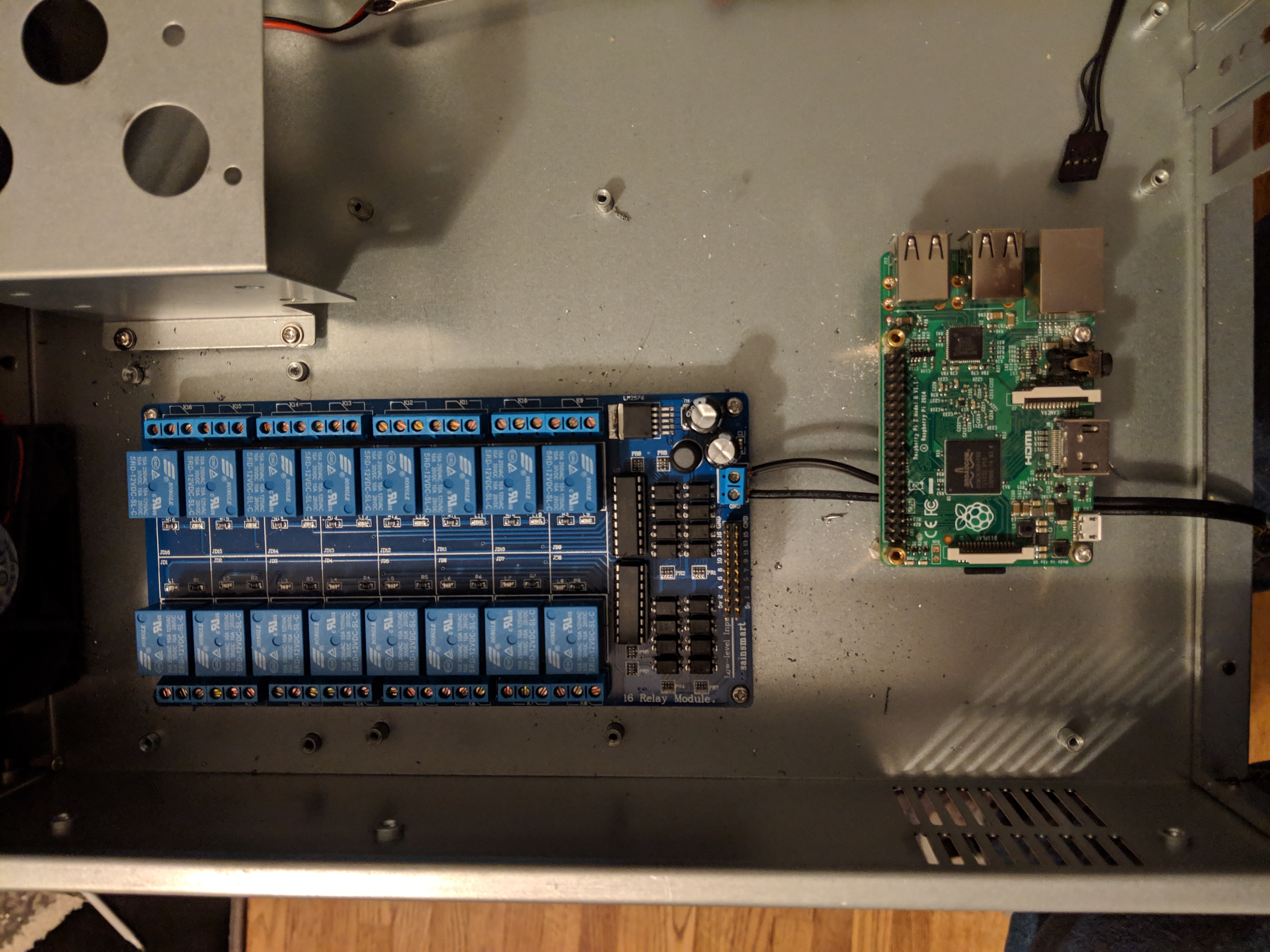
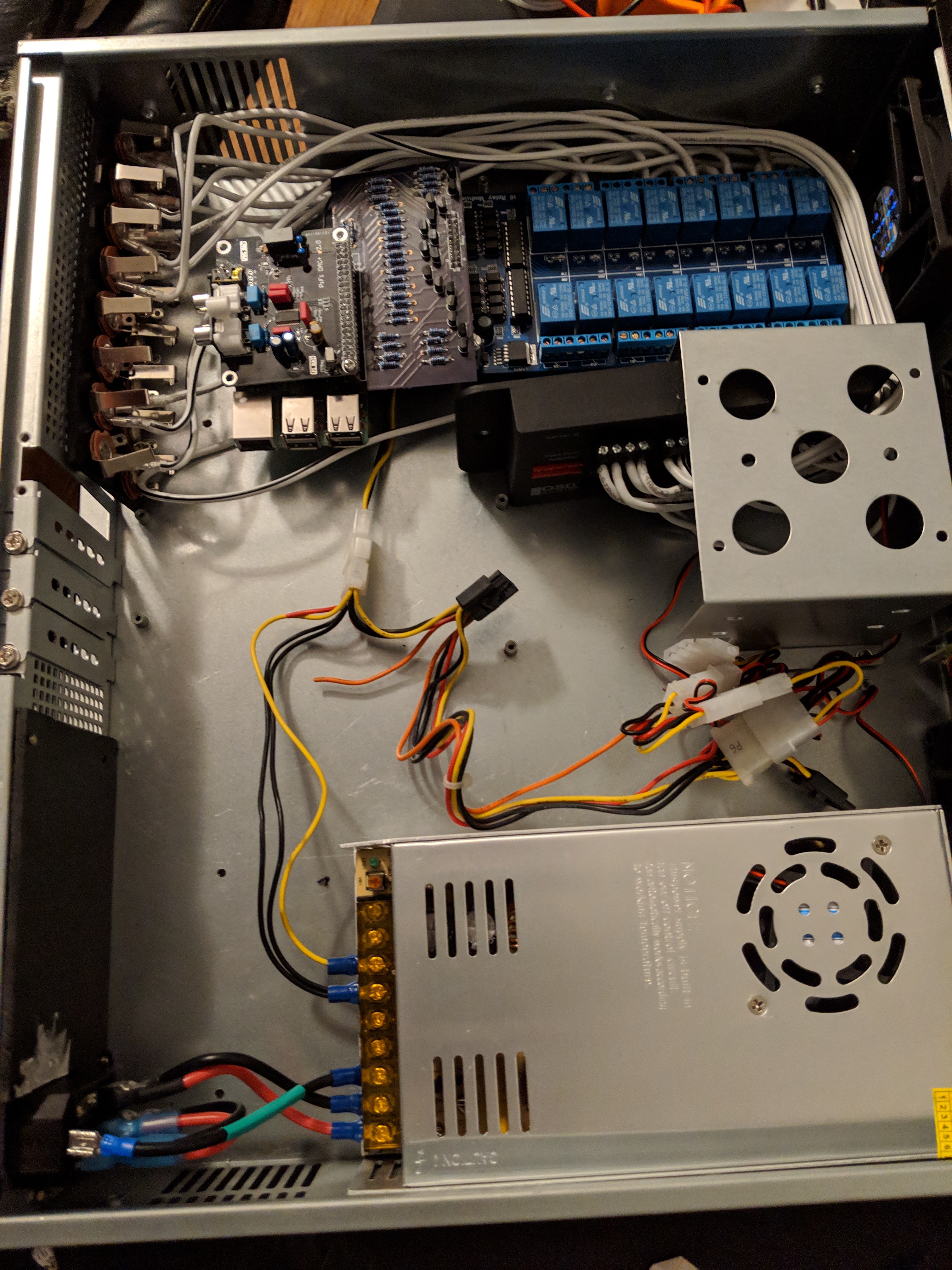
I also grabbed a 2u server chassis to mount it all in. I plan on using the extra space to mount another pi or 2 for other purposes in the same box.
This is a brilliant thread. Thanks for sharing your project, and nice work on the PCB!
Whole-home audio has been on my list of video topics for a long time. I have a few different objectives for it, including:
Distribution of music from a central point out to each room
Pickup of audio from each room and processing at a central point (imagine a voice assistant that is the whole house, not just an object in the house)
Pickup of audio from one point and real-time output at another point (imagine telling your home automation system that you’re in the kitchen, but you want to listen to what’s happening in the back yard while the kids are playing out there)
I’ve gone over a number of different architectures for this. My plan had been to centralise a couple of amplifiers and use a commercial 8x8 audio switching matrix to select speakers around the house and feed them from different sources, so that zones could either play different audio or be bound together.
However, the idea of streaming to distributed head units is also very interesting. My friend Jan Schmidt (who is a GStreamer maintainer) almost has me convinced that streaming is the way to go. Here’s a video of a talk he did a couple of weeks ago about audio streaming and home automation. Near the end it includes a cool demo of selective audio pickup using a microphone array, with him talking from one side of the device and me calling out from the audience on the other with our voices separated based on point of origin:
Using a cheap relay board controlled by either a Pi or an Arduino is a brilliant idea though, so now I’m leaning back towards central amps and a switch!
I’m going to watch your project with a great deal of interest
This has definitely been a huge learning experience.
Relay board video demo with my board:
There’s obviously a couple issues with my board even though it does technically function for the relay control. Changes for when (if) I do a rev2:
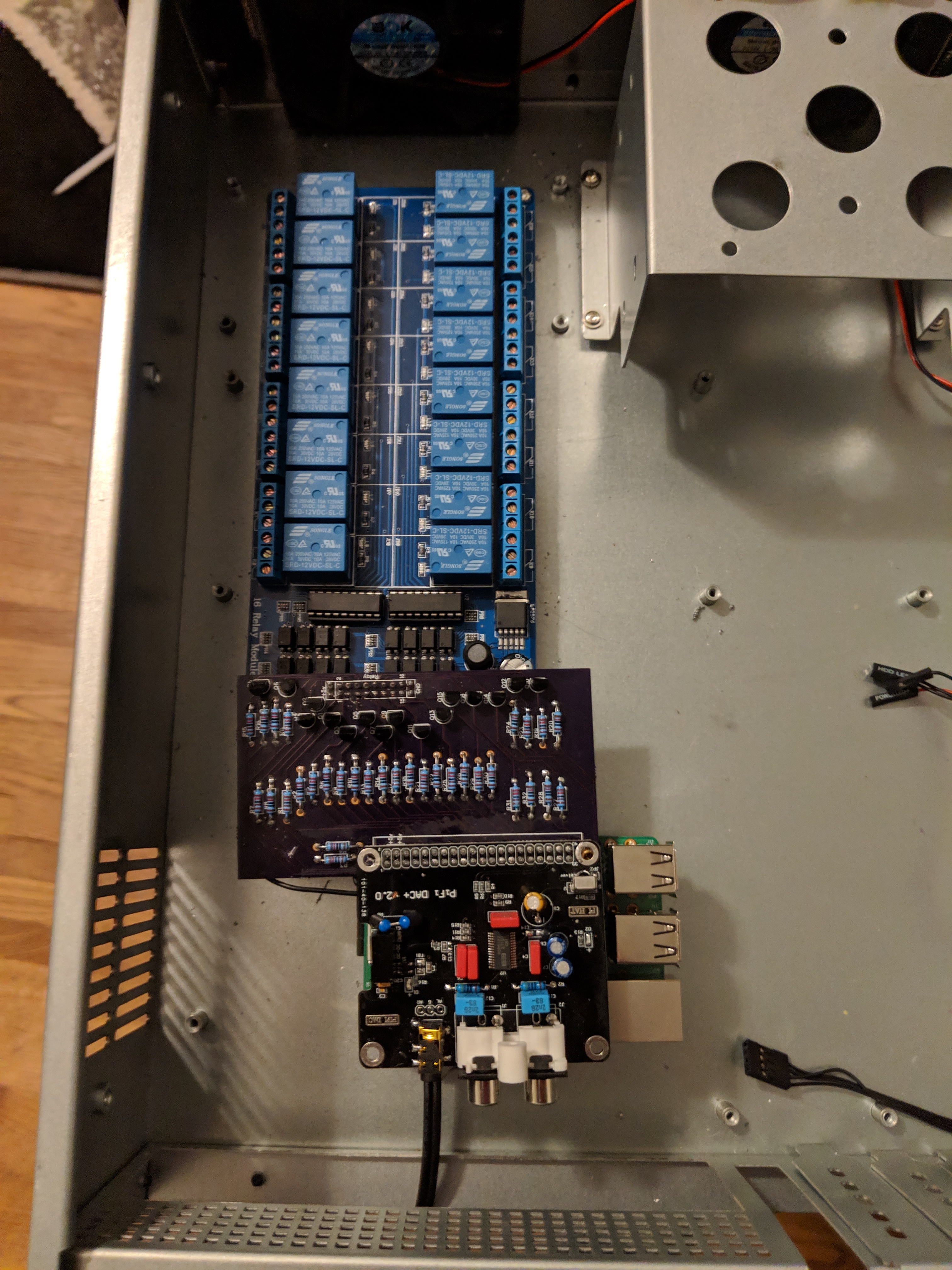
The DAC is getting power through the pins but isn’t properly recognized through the stacking headers. I made sure none of my pins overlapped with the pins it should be using for sound but in discussion with a friend we suspect either we messed up and it does overlap someplace or it’s because the pins I (naively) chose overlap several of the i2c pins. I may cut these traces and reroute with wires or I may just move the DAC to a different Pi.
Space out the transistor pads a bit. Others may not have as much problem as I had but this was an absolute nightmare for me soldering with my shaky hands.
Move the relay board header over so I can properly plug into it without colliding with the tall capacitors on the relay board.
Instead of a revision and reprint of my actual board I may simply use the one I’ve got as-is and either cut the traces and place new wires to switch a couple pins or just keep what I’ve got and use a different pi to go with my DAC. Though a friend suggested I may be able to print my board and sell it to other DIY’ers so I may still do the revision even if I don’t use it for this project.
I like the part of my idea where it’s just a couple boxes in a central location. It’s shortcoming is definitely that I can’t play different things in different rooms. I’ve wondered on a way of using 2 amps to allot for 2 different streams and using another relay board. The current one I’ve got would determine “on/off” and the new one would determine for each speaker whether it’s listening to amp A or amp B. This doesn’t really “solve” my limitation but it does alleviate it a bit simply by changing my limit from “1” to “2” as opposed to a fully distributed system.
The part I’m not AS happy with right now is the smoothness of the audio integration as far as playing whatever it is I want it to play from whatever device I want it to play from and the flexibility thereof. I’m trying to determine if simply I haven’t configured it all enough yet, or if I need to go another route instead of mopidy and upmpdcli.
The way it’s done in commercial audio installations is to use a thing called an audio matrix. 8x8 is common, which means it has 8 inputs and 8 outputs, and it can link any input to any output. What you’ve effectively done is make a 1x8 matrix, with one output switched to 8 outputs. If you look up “8x8 audio matrix” there should be some useful info. Most of them are very expensive rack-mount things, but there’s a really cheap matrix with a serial interface that was connected to an Arduino by a guy in the UK a few years ago. I can’t find the details now though
Next up: strain relief and cable management for the power cord and all the speakers, and getting it listening to MQTT for actually switching the relays.
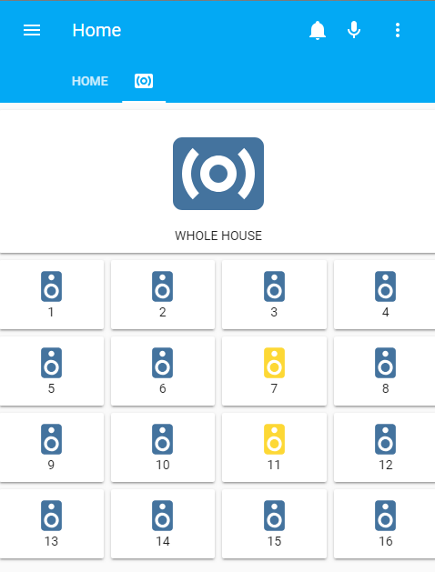
Integration with Home-Assistant works. This is proof-of-concept. When I actually put it in the house I’ll be labeling the speakers more intuitively in the UI as opposed to simply 1-16 (and I probably won’t have all 16). I also added auto-discovery so the speakers get announced to home-assistant as switches, and sets their icon to that of a speaker as well as the appropriate MQTT command topics.
As for the code, once I add proper error handling, as well as making the architecture a bit cleaner and more generic I’ll supply a link to my code on github.
I used a JSON payload to control the speakers. So a command to “home/speakers” with a json payload:
{
    "cmd": "ON",
    "speakers": [0, 1, 4]
}
will turn on speakers 1, 2, and 5 (zero-indexed python array corresponding to the appropriate wiringpi pins).
Additional software changes to do:
The “All Speakers” group is a home-assistant group that simply toggles all the switches - firing 16 MQTT messages. Instead I’ll have it send a single “ON-ALL” or “OFF-ALL” command that does them all and once (reducing the staggered “clicking” sound of the relays as well as the extra message chatter).
Add groups that control the speakers per room (control to only have one speaker on in a given room, or to turn on/off an entire room at once)
Add groups that set rooms into logical aliases. For example, “All Bedrooms”, “Common Areas” (Living Room + Kitchen), as in #1 above it’ll be a single request.
Additional hardware changes:
Add strain relief for the cabling
Once the house is going up and the speakers go in, terminate them into either RCA or banana-plug sockets at the location this setup is going.
After #2: Wire the individual relays into plugs that will go into the wall sockets
After #3: Install the system in a server rack - Amp, Distribution, Relay + pi case
But I think that’s it… I think what I’ve got at the moment is a working system even though I’ve got a bit more polish to go on it before it’s “production-ready”. The house it’s intended for hasn’t even broken ground yet. We’re still waiting on the appraisal.
EDIT: After more thought I’m not liking where the wiring setup is looking like it’s heading. I think I may take the extra room that is in the case and move the audio distribution panel inside of it and mount a bunch of 6.35mm TS sockets on the back. That way I’ve got 1 audio “in” and 16 audio “outs”. I can mount an internal power supply inside so I can use a standard, detachable power cable. I also won’t need a bunch of strain relief this way. I’d hoped to use the extra internal space for another Pi or 2 but I think otherwise this thing will be gnarly and accident-prone.
Now that is what I call taking the ball and running with it! Great job! I too am watching eagerly as you are taking what is generally a commercial only application (affordability wise) and making it something a home-build kind of person can do. Kudos!
I’ve still got to carry the ethernet from the Pi to the back of the box, as well as mounting the outputs from the Pi to the relay, and the inputs from the amp to the relay.
I hope you don’t mind, I’ve started creating categories so that things can be grouped together and I’ve moved this thread into the new “Home Audio” category.
Takes 6 channels for input and 6 channels for output (or 3 stereo input/outputs) but lacks the matrix switching between these. Which is what I’m most interested in. Does anyone know a way to apply matrix switching to analog signals, preferably Arduino controlled?