This has definitely been a huge learning experience.
Relay board video demo with my board:
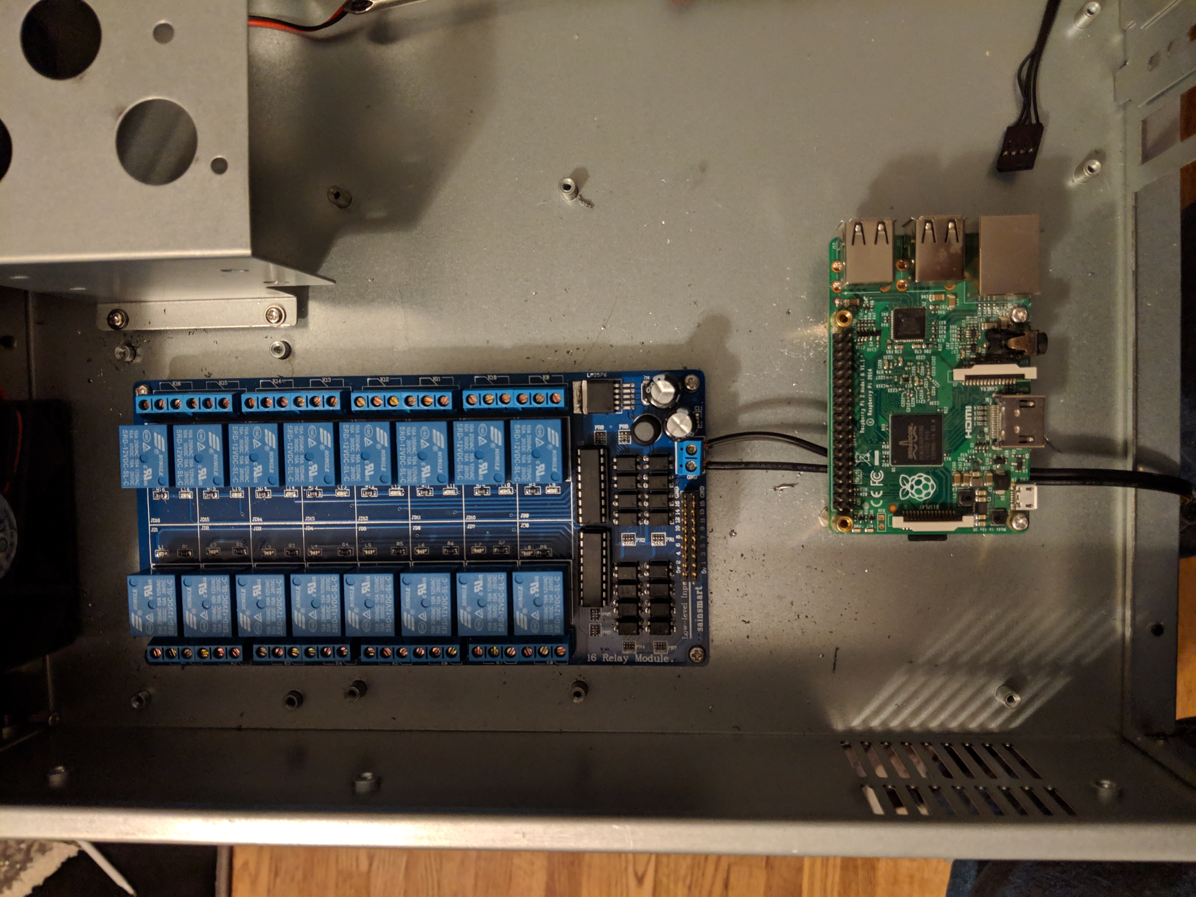
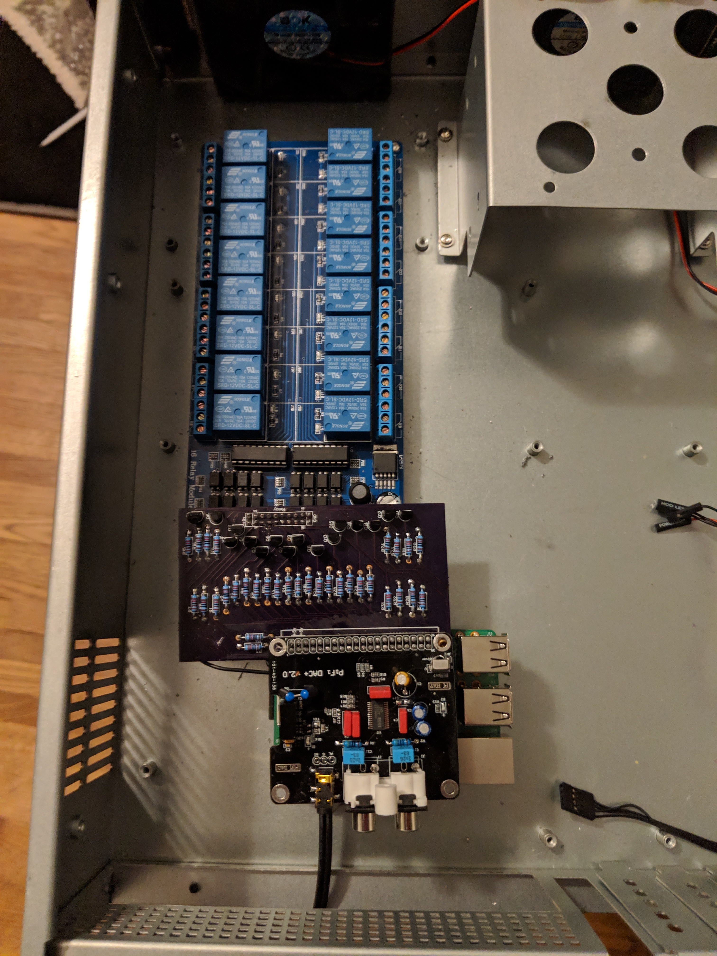
There’s obviously a couple issues with my board even though it does technically function for the relay control. Changes for when (if) I do a rev2:
The DAC is getting power through the pins but isn’t properly recognized through the stacking headers. I made sure none of my pins overlapped with the pins it should be using for sound but in discussion with a friend we suspect either we messed up and it does overlap someplace or it’s because the pins I (naively) chose overlap several of the i2c pins. I may cut these traces and reroute with wires or I may just move the DAC to a different Pi.
Space out the transistor pads a bit. Others may not have as much problem as I had but this was an absolute nightmare for me soldering with my shaky hands.
Move the relay board header over so I can properly plug into it without colliding with the tall capacitors on the relay board.
Instead of a revision and reprint of my actual board I may simply use the one I’ve got as-is and either cut the traces and place new wires to switch a couple pins or just keep what I’ve got and use a different pi to go with my DAC. Though a friend suggested I may be able to print my board and sell it to other DIY’ers so I may still do the revision even if I don’t use it for this project.
I like the part of my idea where it’s just a couple boxes in a central location. It’s shortcoming is definitely that I can’t play different things in different rooms. I’ve wondered on a way of using 2 amps to allot for 2 different streams and using another relay board. The current one I’ve got would determine “on/off” and the new one would determine for each speaker whether it’s listening to amp A or amp B. This doesn’t really “solve” my limitation but it does alleviate it a bit simply by changing my limit from “1” to “2” as opposed to a fully distributed system.
The part I’m not AS happy with right now is the smoothness of the audio integration as far as playing whatever it is I want it to play from whatever device I want it to play from and the flexibility thereof. I’m trying to determine if simply I haven’t configured it all enough yet, or if I need to go another route instead of mopidy and upmpdcli.
The way it’s done in commercial audio installations is to use a thing called an audio matrix. 8x8 is common, which means it has 8 inputs and 8 outputs, and it can link any input to any output. What you’ve effectively done is make a 1x8 matrix, with one output switched to 8 outputs. If you look up “8x8 audio matrix” there should be some useful info. Most of them are very expensive rack-mount things, but there’s a really cheap matrix with a serial interface that was connected to an Arduino by a guy in the UK a few years ago. I can’t find the details now though
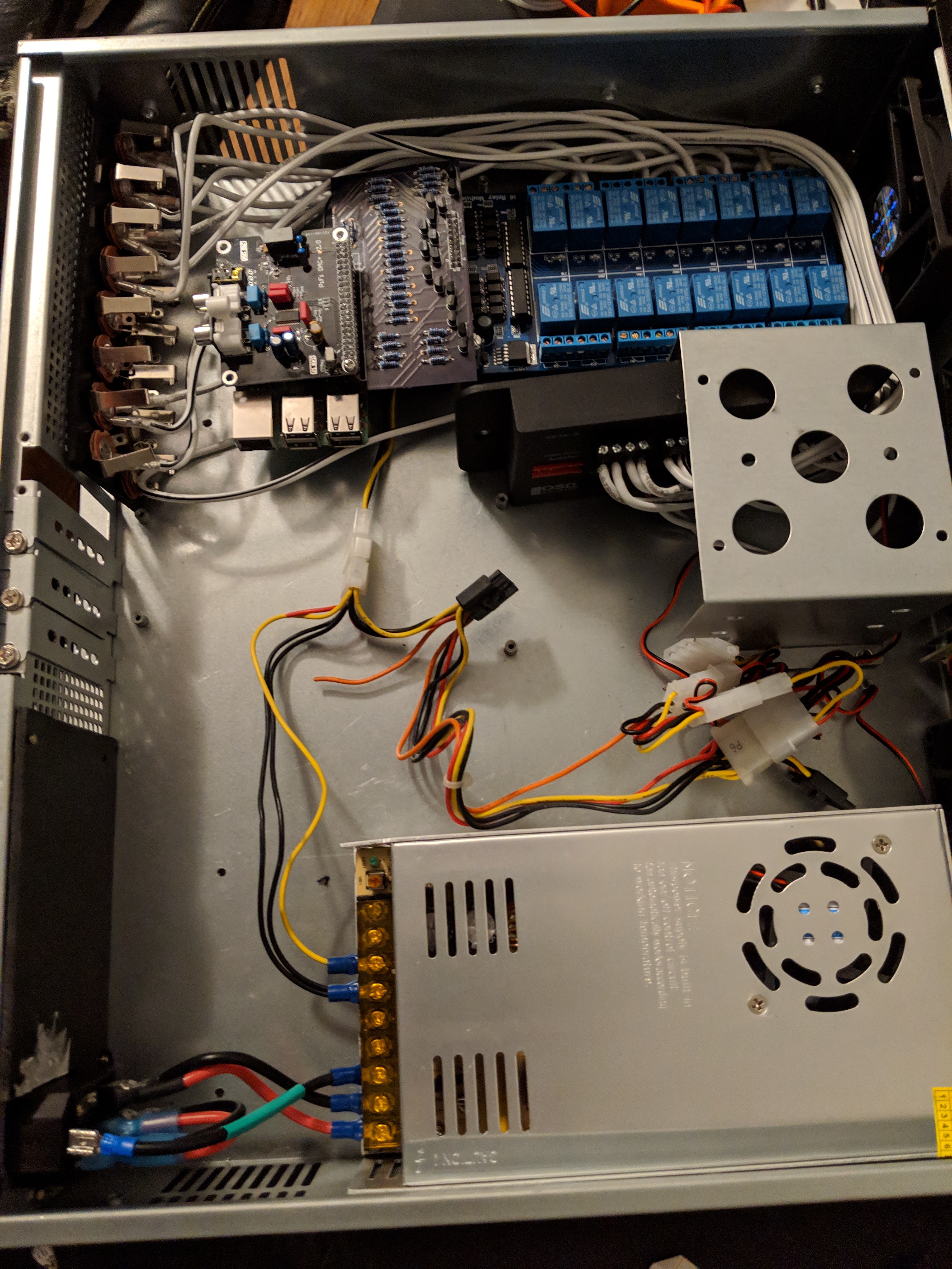
Next up: strain relief and cable management for the power cord and all the speakers, and getting it listening to MQTT for actually switching the relays.
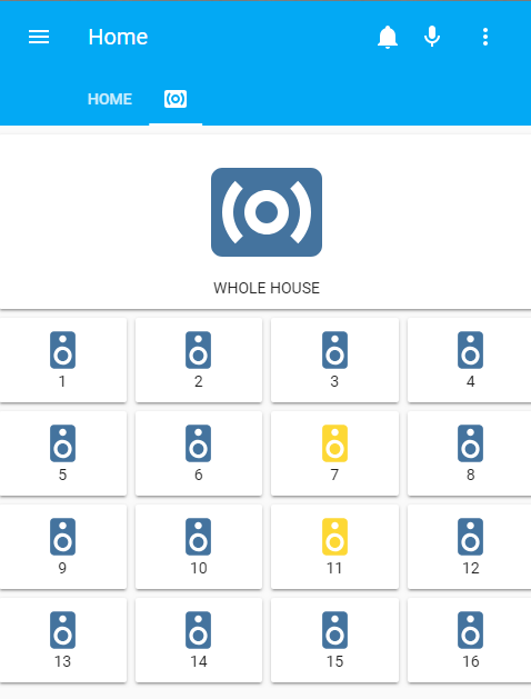
Integration with Home-Assistant works. This is proof-of-concept. When I actually put it in the house I’ll be labeling the speakers more intuitively in the UI as opposed to simply 1-16 (and I probably won’t have all 16). I also added auto-discovery so the speakers get announced to home-assistant as switches, and sets their icon to that of a speaker as well as the appropriate MQTT command topics.
As for the code, once I add proper error handling, as well as making the architecture a bit cleaner and more generic I’ll supply a link to my code on github.
I used a JSON payload to control the speakers. So a command to “home/speakers” with a json payload:
{
    "cmd": "ON",
    "speakers": [0, 1, 4]
}
will turn on speakers 1, 2, and 5 (zero-indexed python array corresponding to the appropriate wiringpi pins).
Additional software changes to do:
The “All Speakers” group is a home-assistant group that simply toggles all the switches - firing 16 MQTT messages. Instead I’ll have it send a single “ON-ALL” or “OFF-ALL” command that does them all and once (reducing the staggered “clicking” sound of the relays as well as the extra message chatter).
Add groups that control the speakers per room (control to only have one speaker on in a given room, or to turn on/off an entire room at once)
Add groups that set rooms into logical aliases. For example, “All Bedrooms”, “Common Areas” (Living Room + Kitchen), as in #1 above it’ll be a single request.
Additional hardware changes:
Add strain relief for the cabling
Once the house is going up and the speakers go in, terminate them into either RCA or banana-plug sockets at the location this setup is going.
After #2: Wire the individual relays into plugs that will go into the wall sockets
After #3: Install the system in a server rack - Amp, Distribution, Relay + pi case
But I think that’s it… I think what I’ve got at the moment is a working system even though I’ve got a bit more polish to go on it before it’s “production-ready”. The house it’s intended for hasn’t even broken ground yet. We’re still waiting on the appraisal.
EDIT: After more thought I’m not liking where the wiring setup is looking like it’s heading. I think I may take the extra room that is in the case and move the audio distribution panel inside of it and mount a bunch of 6.35mm TS sockets on the back. That way I’ve got 1 audio “in” and 16 audio “outs”. I can mount an internal power supply inside so I can use a standard, detachable power cable. I also won’t need a bunch of strain relief this way. I’d hoped to use the extra internal space for another Pi or 2 but I think otherwise this thing will be gnarly and accident-prone.
Now that is what I call taking the ball and running with it! Great job! I too am watching eagerly as you are taking what is generally a commercial only application (affordability wise) and making it something a home-build kind of person can do. Kudos!
I’ve still got to carry the ethernet from the Pi to the back of the box, as well as mounting the outputs from the Pi to the relay, and the inputs from the amp to the relay.
I hope you don’t mind, I’ve started creating categories so that things can be grouped together and I’ve moved this thread into the new “Home Audio” category.
Takes 6 channels for input and 6 channels for output (or 3 stereo input/outputs) but lacks the matrix switching between these. Which is what I’m most interested in. Does anyone know a way to apply matrix switching to analog signals, preferably Arduino controlled?
Super easy, layers of relays!!! I had one sketched out on paper years ago before I went a different route due to video requirements, I’ll try to find my old notes & diagram on my old tablet to post them within the next day or 2… it’s way way easier than ud think it would be… adapting a sketch to control it would be super easy…