That is great, if you have the time to spare. I understand the basics but I am just not connecting on this part. It’s like knowing just enough Spanish to get some food but not enough to find a bathroom afterwards 
So… I was given some great advice on switch…case stuff and an example that is really quite a bit like what I am trying to accomplish as a reference that I have been following. I built my state machine layout and created functions to do the heavy lifting in the code… and couldn’t wade through the timers in 15 different places (functions) to debug properly. I opted to drop most of the functions and integrate that code into my states so I could work state by state and make each one work. Then I can take that working code and create functions to call and clean up my code. So, at the moment, all the work for each state is being done within the walls of each state. I will drop the whole sketch below for your reference… cuz I know it’s vital to have it all in the end… but here is the state that is causing me fits. It is no where near clean enough for me but it is where I last left it at 5AM this morning.
case STATE_TIMER_RUNNING:   //*********************Needs ISR for lid reopen during timer?????
      {

        Serial.println("Timer Operation Has Begun...");
        Serial.println("______________________");

        while (millis() - lockdown_timer_activity >= LOCKDOWN_TIMER){
         lockdown_timer_activity = millis();
        Serial.print("Timer has timed out now...");
        delay(6000); ///Only so I can stop the message scroll long enough            to see what it is doing...
        current_state = STATE_LOCKING_DOWN;
           }
        if ((lid_state != last_lid_state) && (lockdown_timer_activity < LOCKDOWN_TIMER)) {
          digitalWrite(ledR, LOW);
          digitalWrite(int_lights, LOW);
        current_state = STATE_LID_OPEN;
        }
        }

        break;
How I envisioned this reading in plain English is thus: In the previous state, I turned the box lights on and turned the red LED on as well to indicate state change. We enter the state and it gives me a serial print. It starts the lockdown timer and does nothing UNLESS the lid is reopened, at which time it should reset the timer, probably by going back a state to the lid opened state so that the appropriate lights can be turned on/off.
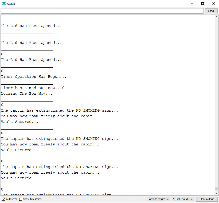
All of my states up to this point work properly… I think. HOWEVER, once it gets to the above state, it does the serial prints and half the time it goes into the timer and half it immediately prints “Timer has timed out now…”, stops at the delay and then books it right past the lockdown and into the locked out state. I don’t want delay() in my scripts anywhere but had to plug that one in just to stop the scroll in the serial windowI have tried if, if…else, while, do… while if…else if… etc in any combination I can come up with and I can’t get the timer to work properly OR the lid reopening in this state causing it to revert back to the STATE_LID_OPEN state to reset the timer. I have no idea at all on what to do to make it see the lid has been reopened BEFORE the timer has completed it’s cycle and then restart the timer.
I am riding the desk tonight at work and will be checking back here really often if you have questions and once I get home (at 0215), I am going to make a quick unlisted video of the process as it is with the board functioning, the code and the serial print window so it is really visually obvious as to what it isn’t doing right. Thanks for your efforts…
The whole code minus the wifi and mqtt section…
/*
 Package Vault Controller for ESP32
 Copyright 2019 theguruofnothing
 Board: ESP32 Devkit V1 (DoIt)
 This controller is the brain for "The Package Vault Project", an open source high(er) security package
 reception device. It was designed with the sole purpose of curtailing package theft. I want others to take
 this design and make it their own. However, I would hope that you would honor my efforts for the greater
 good and not use it for unbridaled commercial gain. Custom designed controller units are available at
 www.superhouse.tv and I hope you come by and check out the community on the Discourse channel there.
 Questions? You can reach me at TheGuruOfNothing@yahoo.com
 */

#include <WiFi.h>
#include <PubSubClient.h>

WiFiClient Vault1;
PubSubClient client(Vault1);

//Timer Intervals
#define BLINK_INTERVAL        800     // 800MS BLINK (RED OR BLUE LED)
#define BLINK_INTERVAL_TOGGLE 500     // EMERGENCY INDICATOR (R,G,B)
#define LID_OPEN_TIME_OUT     120000  // 2 MINUTES BEFORE LID_OPEN MESSAGE TO MQTT
#define LOCKDOWN_TIMER        15000   // 15 SECOND LOCKDOWN TIMER
#define RELAY_TIMER           6000    // TIME ACTUATOR RELAY SHOULD BE ACTIVE IN ANY DIRECTION
#define DEBOUNCE_DELAY        800     // MAG SWITCH DEBOUNCE TIMER

//States
#define STATE_STARTUP       0
#define STATE_READY         1
#define STATE_LID_OPEN      2
#define STATE_TIMER_RUNNING 3
#define STATE_LOCKING_DOWN  4
#define STATE_SECURED       5

//Pin Definitions
#define mag_sw       5  //Lid switch
#define relay_1      18 //Unlock
#define relay_2      19 //Lock
#define int_lights   21 //Interior light strip
#define pir          2  //Passive infrared sensor, internal to box (Panic/Safety)
#define panic_button 4  //Lit button, internal to box (Panic/Safety)
#define ledG         12 //Green LED
#define ledB         13 //Blue LED
#define ledR         14 //Red LED

bool lid_state = 0;
bool last_lid_state  = 0;
int current_state = STATE_STARTUP;

unsigned long last_debounce_time = 0;
unsigned long debounce_delay = 200;
unsigned long blink_interval_activity = 0;
unsigned long lid_open_time_out_activity = 0;
unsigned long lockdown_timer_activity = 0;
unsigned long relay_timer_activity = 0;
unsigned long relay2_timer_activity = 0;
uint16_t last_lid_time = 0;

Wifi and MQTT info here


void setup() {
  Serial.begin(115200); //Change this if using Arduino board

 // We set up the pinmode() and starting conditions
 pinMode(relay_1, OUTPUT);
 pinMode(relay_2, OUTPUT);
 pinMode(mag_sw, INPUT_PULLUP);
 pinMode(pir, INPUT_PULLUP);
 pinMode(panic_button, INPUT_PULLUP);
 pinMode(int_lights, OUTPUT);
 pinMode(ledG, OUTPUT);
 pinMode(ledB, OUTPUT);
 pinMode(ledR, OUTPUT);

 //Set the relay's to off to begin with or they float partially active...
 digitalWrite(relay_1, HIGH);    //Relay board requires these HIGH to be off
 digitalWrite(relay_2,HIGH);     //Relay board requires these HIGH to be off
 digitalWrite(int_lights,HIGH);  //Relay board requires these HIGH to be off


//Start up Wifi connection
   WiFi.begin(ssid, password);

  while (WiFi.status() != WL_CONNECTED) {
    delay(500);
    Serial.println("Connecting to WiFi..");
  }

  Serial.println("Connected to the WiFi network");


 //Connecting to MQTT server and set callback
  client.setServer(mqttServer, mqttPort);
  client.setCallback(callback);

  while (!client.connected()) {
    Serial.println("Connecting to MQTT...");

    if (client.connect("Package_Vault", mqttUser, mqttPassword )) {

      Serial.println("connected");

    } else {

      Serial.print("failed with state ");
      Serial.print(client.state());
      delay(2000);

    }
  }

}

// Defines what info we want (and expect) in our MQTT communications
void callback(char* topic, byte* payload, unsigned int length) {

  Serial.print("State Changing...Message Published on ");
  Serial.println(topic);

  Serial.print("Message Delivered is:");
  String messageTemp;  //Sets string var

  for (int i = 0; i < length; i++) {
    Serial.print((char)payload[i]);
    messageTemp += (char)payload[i];
  }

  Serial.println();
  Serial.println("-----------------------");

  //Subscribe to appropriate topics on MQTT
  client.subscribe("vault/reset");

  if (String(topic) == "vault/reset") {  //Unlocks the box
            if(messageTemp == "1"){
         current_state = STATE_STARTUP;
            }
  }
}

void read_lid()
{
  lid_state = digitalRead(mag_sw);
  if (millis() - last_debounce_time > DEBOUNCE_DELAY) {   //Debounce Timer
    last_debounce_time = millis();
  }

  if (lid_state != last_lid_state) {   //check if the button is pressed or released
    last_lid_state = lid_state;
  }
}

void blink_led_toggle()
{
  unsigned long led_toggle = millis();
  //Blink the RED LED at once per second...until the reset request is received
  if (led_toggle - blink_interval_activity > BLINK_INTERVAL_TOGGLE){
      blink_interval_activity = led_toggle;// Update the time for this activity:
  digitalWrite(ledR, !digitalRead(ledR));
  digitalWrite(ledG, !digitalRead(ledG));
  digitalWrite(ledB, !digitalRead(ledB));
  }
}

void panic_check(){  //This is a kill switch for the box. Forces an unlock and then locks the processor in an infinite loop
                       // to prevent any possibility of resetting and relocking
   int PANIC1 = digitalRead(pir);
   int PANIC2 = digitalRead(panic_button);

   if(PANIC1 || PANIC2 == LOW)  // Something has gone very wrong and box needs to be unlocked NOW!!!
   {
  //  unlock();
    blink_led_toggle();

    Serial.println("Emergency Protocol Activated");
    Serial.println("A failure has occurred and vault has been disabled. Power must be cycled to reset");
    client.publish("vault/state", "Panic");

    while(true) {} //I want to kill the process so there is no way to restart the  main loop unless power cycled
             //so I created an infinite while() loop to do that. Probably a more elegant way to do it
             //but let's face it, if this protocol has to be enacted, shit HAS hit the fan...
  }
}

void loop() {

  read_lid();     // Update the lid status
  Serial.println (lid_state);
  client.loop();   //Loops connection with MQTT subscriptions

  switch(current_state){

      case STATE_STARTUP:
        {
        Serial.println("Startup In Progress...");
        Serial.println("______________________");
        digitalWrite(relay_2, LOW);  //Starts actuator power
        // start up the relay run timer
        if (millis() - relay_timer_activity >= RELAY_TIMER) {
        relay_timer_activity = millis();
        digitalWrite(relay_2, HIGH);  //Stops actuator power
        digitalWrite(ledG, HIGH);
        current_state = STATE_READY;
        }
        }

        break;


      case STATE_READY:
      {
        Serial.println("Ready For Packages...");
        Serial.println("______________________");
        // If lid is opened
        if (lid_state == 1){
         current_state = STATE_LID_OPEN;
        }
      }
        break;


      case STATE_LID_OPEN:
      {
        Serial.println("The Lid Has Been Opened...");
        Serial.println("______________________");
        digitalWrite(ledG, LOW);
        if (lid_state == 1)
        {
         //Blink the BLUE LED at once per second...until the lid is closed
        if(millis() - blink_interval_activity > BLINK_INTERVAL){
        blink_interval_activity = millis();// Update the time for this activity:
        digitalWrite(ledB, !digitalRead(ledB));
         }
         if (millis() - lid_open_time_out_activity > LID_OPEN_TIME_OUT){
         lid_open_time_out_activity = millis();// Update the time for this activity:
          client.publish("vault/lid_ajar", "TRUE");
        }
        }
        else
        {

          digitalWrite(ledB, LOW);
          digitalWrite (int_lights, LOW);
          digitalWrite(ledR, HIGH);
          current_state = STATE_TIMER_RUNNING;
        }
      }
        break;


      case STATE_TIMER_RUNNING:   //*********************Needs ISR for lid reopen during timer?????
      {

        Serial.println("Timer Operation Has Begun...");
        Serial.println("______________________");

        while (millis() - lockdown_timer_activity >= LOCKDOWN_TIMER){
         lockdown_timer_activity = millis();
        Serial.print("Timer has timed out now...");
        delay(6000); ///Only so I can stop the message scroll long enough to see what it is doing...
        current_state = STATE_LOCKING_DOWN;
           }
        if ((lid_state != last_lid_state) && (lockdown_timer_activity < LOCKDOWN_TIMER)) {
          digitalWrite(ledR, LOW);
        current_state = STATE_LID_OPEN;
        }
        }

        break;

      // ****************not working through this point**********************************
      // or gets past this point and blasts to STATE_SECURED


      case STATE_LOCKING_DOWN:
     {
        Serial.println("Locking The Box Now...");
        Serial.println("______________________");
         digitalWrite(relay_1, LOW);  //Starts actuator power
        // start up the relay run timer
        if (millis() - relay2_timer_activity >= RELAY_TIMER) {
        relay2_timer_activity = millis();
        digitalWrite(relay_1, HIGH);  //Stops actuator power
        current_state = STATE_SECURED;
        }
     }
        break;


      case STATE_SECURED:
     {
      uint16_t time_now = millis();
        Serial.println("The captin has extinguished the NO SMOKING sign...");
        Serial.println("You may now roam freely about the cabin...");
        Serial.println("Vault Secured...");
        Serial.println("______________________");
         //Blink the RED LED at once per second...until the reset request is received
        if(time_now - blink_interval_activity > BLINK_INTERVAL){
        blink_interval_activity = time_now;// Update the time for this activity:
        digitalWrite(ledR, !digitalRead(ledR));
        }
          panic_check();  //Check if the panic indicators have been tripped after the lockdown has occurred
     }
        break;
     }
     }

 I have what is pretty close to a working sketch but am really stuck on a part of it that I can’t debug. I was offered some assistance in figuring it all out so I have fired off the code and am waiting to see what guidance they have for me. I know it is something stupid like not declaring something important or improper syntax. It’s mostly my ignorance… but I can fix that!!! I don’t want to post broken code to Github but if anyone wants to bore themselves to death, I can drop it on here. I planned to do a video of what is going on when I get off work early in the morning today.
 I tried yet another idea…