Universal smart 5 button light switch - can you help me with my project?

Hello,
I am working on a smart light switch with 5 buttons, which is supposted to replace my old, “dumb” light switches. The design is inspired by IKEA TRÅDFRI remote controllers. The 4 small buttons should control each light in the room individually, or switch scenes when held. The middle one is for turning off all the lights, when leaving the room with one click and turning them back on, when entering. I already have some expirience with tasmota (several sonoff devices) and also designing my own simpe circuits, (for example my led bar dimmer) which also runs tasmota. All the logic is done in NodeRED and the rest in OpenHAB.

However this project is little more complicated by the fact that all the circuitry needs to fit in the existing light switch box and I can’t run any extra wires (we live in a brick, Central Europian house). I can only use whats already there, meaning 220V AC mains.

I have came to a conclusion, that the best idea is to design my own circuitboard and have it printed by JLC PCB or some other company. The circuit should have 5 buttons, wemos D1 mini, ac power source, mains relay and ideally a ws2812 led to indicate the current scene.

Here is a little schematic for visualisation

The problem is that I can’t figure out how to connect the relay to make it work. I have this small Hi-Link power supply because I don’t wanna mess with mains too much creating my own power supply. And also, can you please help me with making the shematic suitable for printing? I’am not sure if I want to go with SMD or through-hole components, because I don’t own a soldering iron good enoug for soldering SMD yet. Or is my idea all wrong? Should I do this somehow else? Ahhhh :smiley:

Any help would be greatly appreciated!

My discord name for contact: ThatMineMac #1127
// I’am sorry for any language mistakes, I am not a native speaker :slight_smile:

That is a tall order. That is a LOT to put onto one tiny little board. Will be interested to see what you come up with though. Sounds a lot like a Shelly module with Tasmota and rules engine.

Sounds like a fun little project… Go the SMD!!!

I found that a good pair of tweezers and a magnifying glass, are more important than the soldering iron when you’re a beginner. I did my first SMD with a seriously crappy cheapo soldering iron from one of those starter kits. And If you can do a schematic, you can do a PCB layout. That SMD board I mentioned was from Getting to Blinky (though an earlier version, where he’d made a mistake that I dutifully copied because I figured surely he knows what he’s doing more than I do). Though, expect to mess up the first one, and also expect to have to re-spin your first board. My first one actually worked, once I realised that Chris had in fact made the mistake I was worried about, and so lifted one leg of the IC up in the air. But I did a new board with the problem fixed, and some other minor tweaks, and then put all three together for practice. I was actually most happy with the second last one (the first two were a bit gruesome), and when I decided to do a 3rd version, a keyring sized one, I didn’t have any trouble at all — which was good because I also only had one IC left, having expected to mess up more than I did. If you are worried, or just haven’t finalised the design just yet, perhaps hit up one of the many tutorials and get some practice in first. Go with the nice chunky 1206 resistors, and you should be fine. You’re planning on using modules for all the fiddly stuff anyhow.

I hope your rules for tinkering with mains are better than ours here…

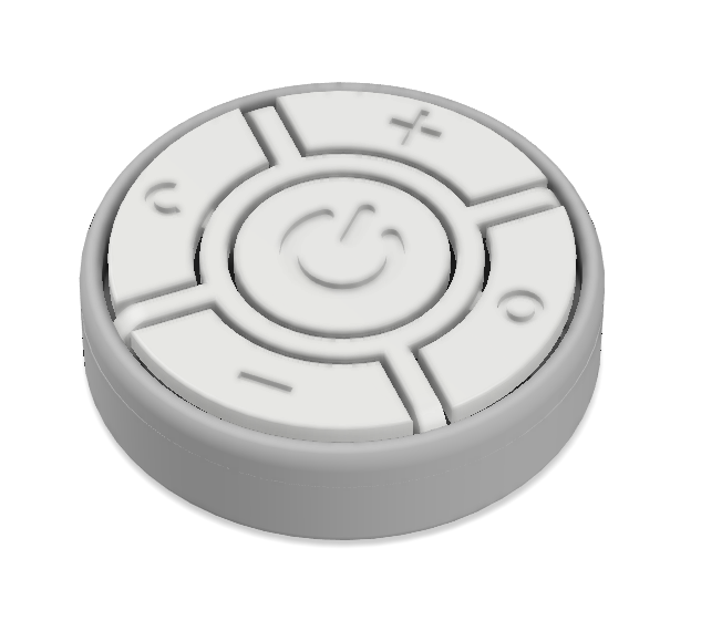
Personally, it sounds like I’d probably put the buttons, and LED on the front, and the resistors and D1 module on the back, with the power and relay on a stand-off, and going SMD avoids leads poking through in awkward places, and unsightly solder blobs showing through between the buttons.

The relay typically needs a transistor and flyback diode (I think they’re called — it’s been a while). The transistor likes to have a current limiting resistor (otherwise it tends to do nasty things to the ųC), and the diode is just a regular reverse biased power diode to catch current spikes kicked back from the coil when it turns off. You can find plenty of material about that on good ol’ Google. I’m not entirely sure why relays are so much more popular than triac’s or SSR’s or whatever (maybe someone better at that stuff can answer that for me, too), also, are latching relays a viable thing? The ones that just stay in whichever state you put them last.

As for scenes… This is part of a system. So pull the actual control back into a dedicated device, otherwise, you’re going to have to keep every switch that has any scene device in common, perfectly in sync, all the time. That’s not real difficult, and improves redundancy, but also makes it more complex, prone to glitches and desyncs, and a general pita. Another problem, however, is that it makes it hard to mix and match hardware, because every switch now also has to understand every device, and listen for updates to every device, and it ALL had to remain in sync. That’s fine if you have a nice heterogeneous system, but then say you want to just quickly add in an extra device for some temporary situation — and now you’re stuck. So split the functions of the device, and do the actual control centrally — when a button is pressed, send a message back to the controller, which sends a message back to the button to actually flip the relay, or change the LED colour. Introduces a little delay, but when everything’s working it should be barely noticeable. That said, the button device can still set it’s LED or switch the relay pro-actively, if the controller always sends back a response command; if the controller then says ‘no’, you’ll get a flicker, and it goes back to how it was. (And you can deal with that by adding in a delay of your own.) Also, since it has a brain, I’d probably add in bit of logic so if the button is held down, or the device notices the server has become unreachable, it goes into “dumb mode”, and behaves like a simple switch for it’s directly connected light until the server returns (or you take it out of dumb mode).

That’s my 2¢ worth, anyhow. (Of course, we don’t have 2¢ coins any more, so, expect it to round down to 0 sense.)

Two things immediately come to mind:

  1. If you’re in Central Europe, do you actually have a Neutral available at the light switch?

Most European wiring schemes have a constant Live going to all the switches and a Switched Live going to each light, with the Neutral on the other side of the bulb.

  1. If you want individual control of four lights, that is going to require four relays, and there is no way you will be able to accommodate those inside an E86 wallbox.

I’m not saying it’s impossible to achieve what you want, but is is going to be physically difficult…

Hello, thanks for all the replies!
@Guru_Of_Nothing Yes! My idea is very similar to Shelly (it is maybe closer to sonoff touch) with the difference in the number of buttons, button layout, the LED and some other details.

I already have some ideas on how to fit all of this in the small electrical box, and make it safe at the same time. The idea is to make one circular board with the buttons and the LED on one side, and the Wemos D1 mini, resistors and 3 pin header on the other side. Please note, that you could use this as a stand-alone unit, when you plug in a micro-usb cable with 5V (for example on a tabletop, etc.).
When you would like to replace a light switch with it where only mains are available, you would connect second “mains board” using the pin headers previously mentioned. The “mains board” would have the relay, 5v power supply and some circuitry for the relay. One of the header would supply the board and the relay with 5V, one would send the relay signal and one for ground.
@Fredderic I believe this would effectively separate the higher and lower voltage circuitry.

For the software, i thought it would be enough (at least for the beginning) to use tasmota, and configure it in a way that every button press/hold is sent to node RED which responds with commands on what to do with the LED or relay. For a fallback scenario, it would act (just like you said) like a normal dumb light switch and control the connected light with the main big button.

@duncan_a Yes, in older Central European houses this was exactly the case, but I were lucky enough and got the house renovated (like 6 years ago, unfortunately I didn’t know anything about smart houses at that time) and wired with neutral (and ground wire) to all light switches, which seems to be the norm now. It is quite smart, because you don’t need any electrical junction boxes along the way. The wires from switch box come straight to the light switch and from the first light switch to another light switch and than to another light switch etc. The only disadvantage is that that all the wires that need to fit behind the switch leave less space for my little project :sweat_smile:

I agree that it would be very hard to fit 4 relays in the small space behind the light switch, and fortunately that’s not what I’am trying to achieve. By controlling up to 4 or 5 or whatever lights I meant sending commands to control them, not actually physically controlling them. The relay actually controls only the light which light switch it replaced. However this doesn’t work for double light switches, that would need 2 relays (maybe version 2.0? :smiley: )

Thanks again for all the ideas and questions. @Fredderic yes, I will go with SMD :smile: and also thanks for all the other tips.

So, now I’am creating a prototype on my breadboard and I have some questions: I used this popular low level trigger relay module which, as far as I understand, means that the relay triggers when the level on the connected pin is low. However when I connect the relay straight to the GPIO, the voltage on the pin is maybe too high to untrigger the relay? and it just stays on. Adding a 10k resistor on the pin sort of fixes this for me, but if you listen closely, you can still hear the relay humming therefore not being “fully” turned off.
So is it better to connect the relay as low or high level trigger? My initial idea was to just copy the whole schematic of the relay module, but now when that won’t work, could you please recommend some other wiring diagram? I have a few 2N2222A transistors, some diodes and resistors on hand, but if you suggest some better or additional components, I can easily go buy them. Next question is what pins should I use? I used up the GPIOs according to this guide D1, D2, D5, D6, D7 for the buttons, D3 for relay and D4 for the LED (yes it flashes the LED on boot, but this could be a bug tuned into a nice feature :laughing:). Is everything with this wiring ok? And also should I connect the buttons to 5v or 3,3V?

Thanks, Michal

You mention the relay not turning off. That seems to imply that the input to the relay board is not seeing a sufficiently high signal for a solid Off condition.
Those relay boards are designed for 5V and that’s what they should have for both their supply and, ideally, their switching input. Having said that, I have successfully run them from a 3.3V switching input (direct from an ESP GPIO) in the past.
Whether they will be happy on 3.3V input depends on the characteristics of the input opto-isolator being used, but, whatever happens, the supply voltage should be 5V, with sufficient current capacity.
You can always level-shift the controlling voltage from 3.3V to 5V using a transistor or FET.
It might be helpful to provide a basic schematic so that we can see what you’re doing and better advise you.

@duncan_a This is my schematic with the relay module connected (outlined yellow). The outlined relay schematic was not created by me, but it should be the correct one for the relay module.

Thanks