This was working fin until i connected the 12V power source to my PIR sensor i tried using 4.7k /1k /2.2k at first but the difference wasn’t big enough for the ESP to get.
Hey there! I am wondering what PIR sensor you are using for your project? I would be curious to see what the schematic of the sensor looks like because, as it is drawn, there would be no way for the ESP32 to actually get power from the sensor (module?). Do you have a model or part number from the sensor? I am guessing you were powering the ESP32 on it’s own and disconnected it’s power when you put power to the PIR sensor? Need a little bit more information.
I’m interested to see more about the power setup too. It’s likely the problem is in that area.
Something you can do to check the operation of the PIR independently of whatever code is running on the ESP32 is to put a multimeter with the black lead on GND and the red lead on the ESP32 input, and put it into voltage range. With the PIR powered up, it should operate and as it changes state you’ll see the voltage change at the ESP32 input. That’s the voltage you’re trying to detect, so the first thing is to verify that it’s actually changing to sensible values depending on what the PIR does. If the voltage isn’t changing, there’s nothing you can do on the ESP32 to make it work.
thank you john i will test that.
What i did while setting up is manually shorting the Alarm contacts with a wire as if it was “closed” temper worked by clicking the “temper” switch manually
I made a video about it but it is 4 hours long and must be boring i will try do explain it in anoter on at some poingt
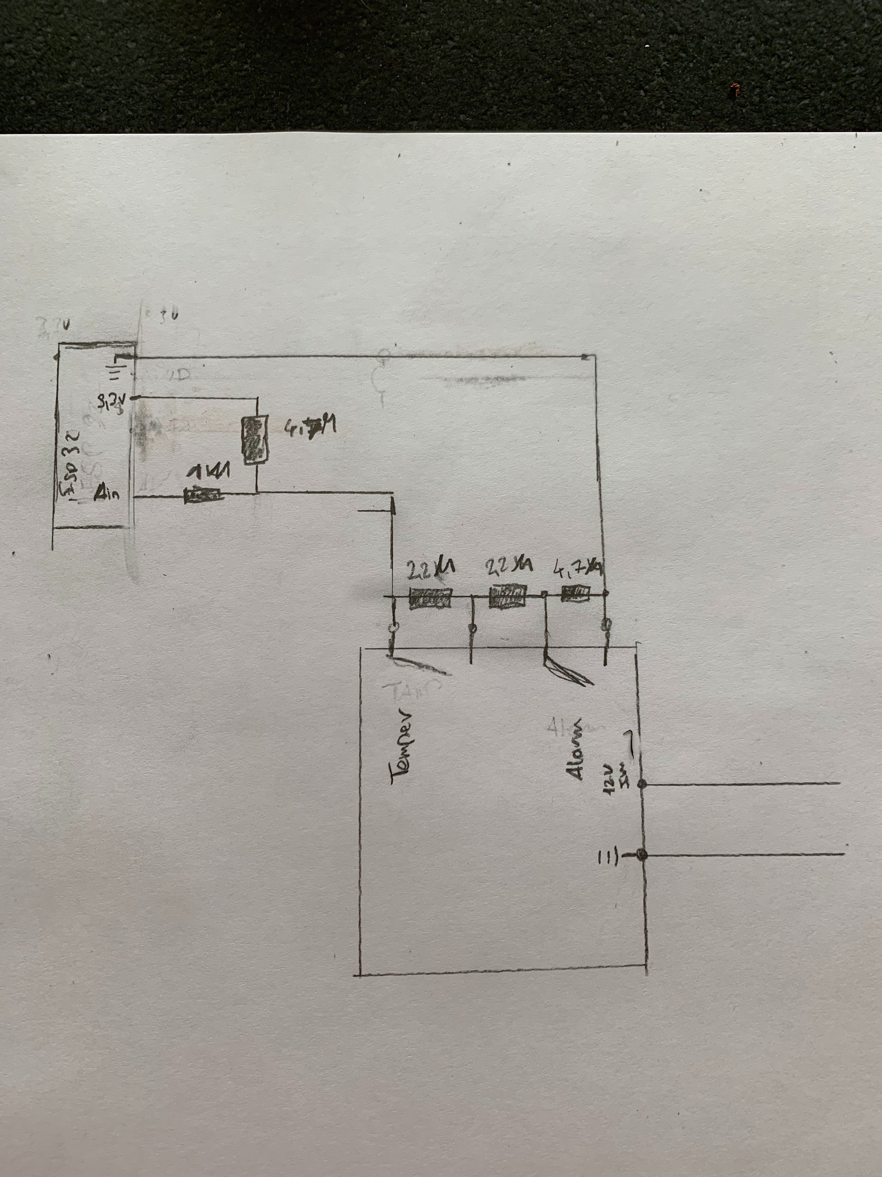
Well… Let me explain a little bit of how the PIR connections are supposed to go and maybe that will shed a little light on what exactly you are trying to accomplish with it. Obviously, there is the 12v input connection to power the PIR unit. It has a “tamper” circuit and an “alarm” circuit.
The “tamper” circuit is an input loop for the sensor that you would normally hook a switch or button to. Most typically, that is a magnetic reed switch connected to a door of a security cabinet. It is ALWAYS a normally closed circuit bridging the two terminals of the “tamper” connections. Since that input is generally used to let the system know someone opened the door to the security system (usually unauthorized), it triggers an automatic and instant “alarm” output. The “tamper” terminals would not be connected to the ESP32 at all unless there is a use I am not aware of (which is quite probable). It could be wired to an external switch for a manual trigger though.
The “alarm” terminals can be jumpered for normally open or normally closed with the “O/P Select” jumper on the PIR sensor unit. So when this thing powers up, it will either open or close those terminals depending on what position you put the jumper in. I did note that the PIR module has a 2 MINUTE startup delay. So once you put power to the thing, go grab a cup of coffee because it takes a bit for it to get fat and happy. It isn’t going to do anything until it has fully started up. The “alarm” terminals are going to be what you would use for a trigger to the ESP32 when the sensor sees motion. In that, I would assume that the O/P should be set for NO so that when motion is triggered, it bridges (closes) the “alarm” terminals, closing the trigger loop you wired to the ESP32 pins. So it would be as simple as 3.3v to alarm terminal 1 and alarm terminal 2 goes to an analog in pin on your ESP32 board. No additional resistors needed. The ESP will need it’s own power supply or a buck converter pulling from your 12v supply to provide the 3.3v needed for the ESP.
Thank you Very much for your explanation i’m afraid that the issue here is me trying to explain what i want to do actually
here the video i was inspired from Jon gave an amazing explanation on this one
I totally forgot about that video Yes, your drawing makes sense now. You will need to put power to both devices and use a multimeter to check voltage between the ground and analog in pins while operating the sensor. My assumption is that because you are at 3.3 volts instead of 5 volts, the voltage that the ESP32 is trying to see is too low for it to sense. That will require lowering the resistor values to bring it up. You are wired correctly according to his schematic. Where I don’t have the knowledge is what the threshold is on an analog read… what the board can effectively see 0-3.3v wise. The other part is what the coding is for the board to make it operate. Still learning that… sorry…
Thank you, well you wouldn’t believe it but i am using EspHome. It’s a custom yaml to C++ code written by someones from the HomeAssistant community
it isn’t as powerful as C++ as of yet but a lot of thing are already converted and so easy to understand
I can read from 0.0 -> 3.3 (3.9V says the log)
I miht have to reduce the Resistors i am currently using 4.7M 2.2M 1M instead of 4.7K 2.2K and 1K
Well this is Strange … or maybe not ? as soon as i connect everything up with the ESP (No power connected ) the resistance drops on my Resistors so for temper i measure 1.8K instead 2.2K and for alarm i get 3.3K instead of 4.7K i must be to dumb to operate that thing or is the ESP bad?
 Yes, your drawing makes sense now. You will need to put power to both devices and use a multimeter to check voltage between the ground and analog in pins while operating the sensor. My assumption is that because you are at 3.3 volts instead of 5 volts, the voltage that the ESP32 is trying to see is too low for it to sense. That will require lowering the resistor values to bring it up. You are wired correctly according to his schematic. Where I don’t have the knowledge is what the threshold is on an analog read… what the board can effectively see 0-3.3v wise. The other part is what the coding is for the board to make it operate. Still learning that… sorry…