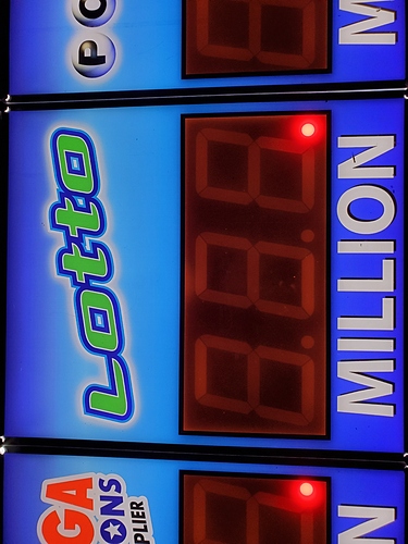
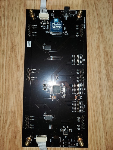
Ok, so today the wife brought me home a zigbee powered lotto sign she found in the dumpster @ work, it contains 3x 8slot dip switches and an xbee made by maxstream as the controller. i would like to re-program it but theres zero documentation available and only have arduino/general atmega programming experience… not sure if i should try to re-code the zigbee or drop in an arduino and start from scratch… any advise/ comments are openly welcome as im not a zigbee person at all… im willing to learn a new platform but thought id see if the community has any better or interesting ideas before i proceed…
First point is that this may not even be using Zigbee, but I’ll get back to that.
Is there any other microcontroller on the main PCB?
Those XBee modules can be used in a couple of different ways. The most common method for hobbyists is to treat them as an RF-to-Serial bridge, basically like a modem controlled using AT commands. This requires a separate microcontroller somewhere else on the board to handle the logic of parsing messages, driving the displays, etc.
The other method is to use its own I/O pins to control devices such as the displays directly. This can be done either by loading custom firmware on the module directly, or using the factory firmware and using it to control I/O pins using messages over the air. In either of those cases, you probably have a lot of work figuring out what it’s doing.
Back to the first point. XBee modules can implement the Zigbee protocol, but they often don’t. Zigbee is a protocol that defines how parts of the network layers work, but it’s not the only protocol that can be used on XBee modules. AFAIK it’s more common with those modules to not use Zigbee, but instead use one of the other direct or mesh protocols. Zigbee is just one of the protocols that can be supported by that hardware, depending on what firmware is loaded.
-
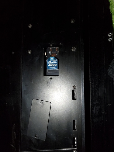
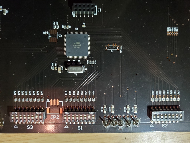
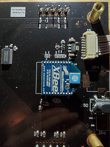
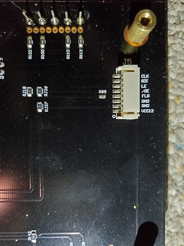
Well it turns out you were exactly right!! I opened it up and this is what it contains!!
-
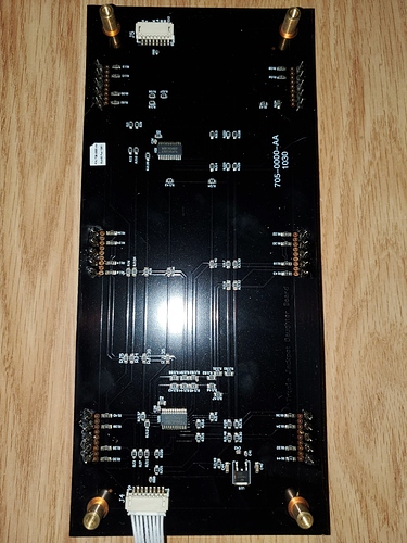
Board 1 & 3: (Identical Slaves)
-
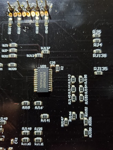
Chip on Board 1 & 3: (All the same)
-
Board 2: (Master)
-
Main Processor: (Thanks Jon!!)
-
Xbee module: (this is definitely getting removed)
-
And even a labeled bus connector!!!
-
And now I’m going to extensively read some datasheets!!
Yes, that seems like a sensible design, just what I’d expect to see. The main microcontroller is obvious (the ATmega, same family as a typical Arduino but a different model) and the MBI5016 is a 16-bit constant-current LED driver.
This is a situation where you have to weigh up the effort vs reward: you could write custom firmware to run on the ATmega, communicating via the XBee module and driving the LED drivers, but is it worth it? It would be a fun learning experience, at least.
Seems like that would be a lot of work for some 8 segment displays  But if conquering an unknown device is your thing, that is a perfect specimen! Must be a WA lottery sign for storefronts
After much googling, reading, and physically probing it, i have gotten the atmega64 chip added to my adruino ide. I traced back what im fairly certain are the programming pins and am working on a adapting 8bit shift register code to work on these 16bit shift register led drivers… im deffinitely replacing the xbee with either an esp8266 module or an arduino & w5100 as i dont have anything else xbee related… (might try to listen to my xbee based utility smart meters with it at a later date) Its not VA lotto (im in IL) but as far as i can tell most state lottos use these exact same signs… (they threw this one out because the super generic 12vdc power pack died!!) Ill post a more complete walkthrough of how to easily adapt them in case anyone else finds one and wants to make something unique… mine is going to be a 3 zone temperature display with custom plexiglass graphic inserts to replace the 3 lotto inserts…
Very cool… I look forward to seeing the project
Project will be on hold (aside from code cleanup) for about a week until i get an isp programmer to replace the bootloader on the atmega64…
