New option for 8-16 chanel lighting relay board

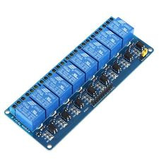
There is a new option for controlling an 8 or 16 channel relay board. You know, those really inexpensive boards for an arduino or a Pi. They typically cost between $4 and $8 everywhere. I want to use them for my lighting control boxes. Mainly due to their low cost and ease of programming.
image

I like lots of lights and lots of control so I need lots of relays. Getting 8 relays for $4 is too good to pass up. Also, they use listed relays (cRUus) so that might help my inspections, my biggest problem.

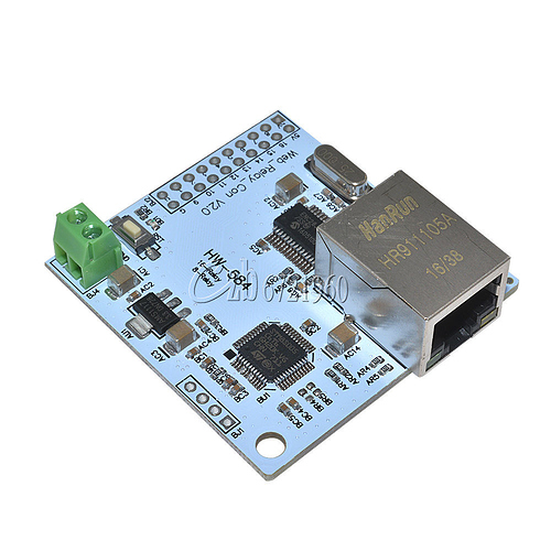
I was going to control them directly from the pins of my Orange Pi One boards using a voltage shifter, 3 to 5v, but I think I found a better solution. This little board, I found, costs only $8 each, including shipping. It plugs onto the relay board and has an RJ45 network jack on it that allows me to control the relays using a network connection. This should eliminate a lot of extra wiring, simplifying the whole lighting system. Also it will allow me the option of putting lighting control boxes anywhere I need to without having to include control logic boards. I can centrally locate all of my control in one panel and send the control codes to the individual relay panels, closer to the lighting.

You can buy the relay boards with the net card as a unit but the price I ridiculous, going up to almost $30 for the same product.

image

I still have a lot of work to do before this is a done deal but my boards came today so I plan on bread boarding up a box and see if I can get all of the bits and pieces to work correctly. The really great thing about these boards is, I can buy a bunch of extras and keep them on hand in case of equipment failure. This increases the plug and play aspects of the system making it easier to maintain and lowering the “oh crap, the lights just went out” factor. Something we’ve all thought about at one time or another. I would like to build in as much redundancy into the system as I can afford and at these prices, that’s easy.

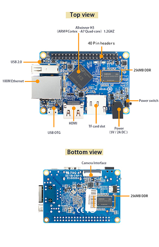
Here’s a picture of the Orange Pi that I plan to use for my button controllers. At $13 each they are a bargain. Also they are $13 each and they have built in RJ45 networking. I like having hard wired networking for all of the boards.

I am going to use a pine 64 for my main brain with Open House, node red, etc. on it. There is an image already made for it with all of the firmware already loaded and ready to go at Open House. At $35 for the pine, it’s a bargain. All of the boards I’ve chosen, besides being cheap, are well supported and readily available. The pine is guaranteed to be available by the mfg. at least until 2021. I will stock at least one extra, loaded and ready to go in case of failure.

All totaled, each 8 channel relay box should cost about $35 each including all of the power strips for the 110v input. I also just purchased a Square D 70A circuit breaker sub panel to power the lighting control panel in my attic. Code requires you to have a disconnect within sight of any remote panel so I decided that having the breakers next to the lighting panel was the best idea… Beats having to put lockout tabs on the main breaker panel on 4 breakers. Two of my lighting control boxes are in the basement equipment panel which is only a couple of feet away from the main panel so no lockouts needed.

That’s a total of 6 lighting control panels for the whole house with 8 circuits in each for a total of 48 possible controlled lights in the house. Some of the relays might control other loads, such as bathroom ventilation fans and such but if I needed more relays it would be easy to swap out the 8’s for 16 channel relay boards for only a few dollars more. One more interesting this to consider is, if I needed a wireless wifi switch, because the relays are network controlled, it would be easy to wire in one using an esp8266 board. I could also add wireless occupancy sensors in the same manor.

Now I just need to program the whole thing to talk to the relay boards. Some instructions I found on one of the sales sites at Ali Express showed this.

Open the browser, the address bar input: http://192.168.1.4/30000 enters the control interface
1, the relay controls the HTTP command:
Relay 1-8 command:
Http://ip/ port /00:Relay-01 OFF
Http://ip/ port /01:Relay-01 ON
Http://ip/ port /02:Relay-02 OFF
Http://ip/ port /03:Relay-02 ON
Http://ip/ port /04:Relay-03 OFF
etc.
Shouldn’t be too difficult to come up with a program to control the relays over tcp-ip. Worse case scenario, it looks like there is a place for a serial header on the board for uploading firmware. I think the network chip on the board is a pretty standard one and there should be some more information on the net about programming. I’ll let you know what I come up with as soon as I get the time to do the bread boarding. Right now I’m knee deep in wiring the home run lighting to the plywood panel backer board in the attic, where the lighting panels will be mounted. It’s summer here and the attic has been in the 90deg F plus temperature every day. Kind of slows me down when I’m roasting and working at the same time. Too many water breaks. This was a lot easier 20 years ago. Getting olds a bitch, as they say. If I don’t die of heat stroke or dehydration, I update this post soon, at least with more pictures.

MisterFixIt1952
I will be really interested to see how that works as far as the inspection goes. I don’t know how much of a stickler the inspectors will be when it comes to that kind of a product as I have never crossed that path. I don’t understand why here in the US, that the products that are developed can’t be DIN rail mounted just like in Europe. It’s not that difficult, it’s not that expensive, and it’s essentially the same crap. It’s also a much more Universal and easily implementable system. The majority of our electrical Hardware here in this country is difficult to work with and does not suffice for home automation without it costing far too much money.

Sounds interesting! Yes - they relay modules themselves may be UL listed; but the pcb is likely not. What voltage are you switching with it?

All my relays are 5v. The controlled voltage is 110v 15A. I have a DIN mounted power supply of 5V 4A for each of the light boxes. That should give me enough power for the 8 channel relay board and the board controller.

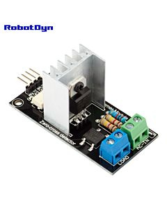
The one thing that has been holding me back is that I really wanted to use latching relays for the lights. Latching relays hold their state after a power outage or logic failure. The thing is, no one that I know of sells an 8 channel latching relay board. The boards I have found have only 1 relay and run about $3 each. Also I would need to use DIN rail board mounts for each relay. This could actually work to my advantage since the long term plan is to add zero crossing dimmer boards to each lighting circuit. Except the closet lighting, stairs etc. I really like having dimmer capabilities for all of the main lighting zones. I have planned on dimmers, having bought dimable LED bulbs for all of the fixtures. I finally found a dimable lighting controller that uses PWM to control the level and were only $4 each including shipping. I ordered 5 of them and they just arrived so I will see how they perform.
https://robotdyn.com/catalog/modules/relays-switches.html
image
I haven’t decided how to integrate these dimmers into the lighting panel yet, but I can either replace one of the relays or wire the dimmer into the relay. It might work well to wire the dimmer into one side of the relay so when you turn off the light, you kick in the dimmer circuit. If the dimmer is off the light will turn off, but if the dimmer is on, you can immediately repress the button to make the dimmer go up or down by holding down the button. All of this will be in software so I need to breadboard a circuit and try out some ideas. Either way, I would like to use only one button for each light control, dimmer or not, but I’m not adverse to using one button for on/off and one for dimmer control up/down (by holding down the button). This 2 button approach would make it easier to keep lighting levels at a set point and also control scenes. As far as scene control, that could be done through the house web page, grouping lights together at preset levels, controlled by the second button with the first button being used for on/off only. Let’s face it, at $1.50 per button, using 2 buttons for extra control, isn’t a bad idea. Since you can connect 5 maybe 6 buttons, using 1 cat 5e cable, wiring is pretty easy. As it is, I plan on running 2 cat 5e cables to each switch, just for redundancy and future expansion. Wire is cheap.

As an additional backup, I am using flexible conduit from each switch to the control panel in case I have problems and need to change or add wiring, at some future date. Using this scheme gives me the flexibility to add touch screens or other upgrades, at some future date. I could retro-wire the system, back to standard 110v wiring, although that would only happen if I had a total meltdown with the inspector.

Speaking of inspectors, I have been racking my brain trying to come up with a fall back strategy in case the inspector refuses to pass my lighting scheme. I still have been unable to find a reasonably priced panel for residential lighting control. I am convinced that one doesn’t exist. Modern, centralized lighting control, is still out of the reach of DIYers, unless you have really big bucks to spend. Most panels available are designed for commercial use and are way over designed with prices that are ridiculous for the technology required.

I can build an 8 circuit control panel for under a hundred bucks and the equivalent panel from a company like Wattstopper (Legrand) would cost you about $1,500 or more. The bare metal box, without anything in it costs almost $500. Adding just 8 relays adds well over $1,000 to the cost. If you figure that a well wired home has 24-36 lighting circuits, the cost jumps out of site for most people, at least the ones I know. Add on occupancy sensors and daylight sensors and things get even worse. I can do exactly the same thing (for the whole house), using off the shelf components for the cost of one empty WattStopper panel.

I have even given some serious consideration to designing a panel and starting a Kickstarter campaign to pay for UL approval and have a batch produced in China. That might be the only way that this kind of product will ever become available at a reasonable price. It seems that none of the big manufacturers, like Square D, Eaton or Siemens are interested in this niche market. I personally think that this is the logical direction that modern house wiring must go.

If we are going to build actual smart homes, we can’t continue to keep using 100+ year old technology and wiring methods. Using high voltage wiring for switching and sensors makes no sense, as evidenced by all of the slapdash wireless schemes available, whose only purpose is to bypass high voltage wiring and control the lighting directly. Rather than require new construction, by code enforcement, to continue the propagation of outmoded technology, alternative methods must become available to consumers.

The NEC (national electric code) comes out every three years with updates to the published code requirements and it can take another 3 years to implement the new regulations on a regional basis. In the past 10 years the only thing that has come forth, of any consequence, is the forced use of idiot proof outlets and $45 arch fault breakers. All of these advances are mainly there to defeat the Darwin principal and protect the public from them selves. These rules do nothing to advance the cause of smart home construction or energy conservation. As it stands, the NEC is one of the chief reasons why there is no appreciable advancement in smart home technology. We seem to be stuck in a chicken and egg scenario whereby there can be no new rules for smart home technology because there is no technology that is approved.

Low voltage control of high voltage circuits, using home run wiring and logic control, is the next evolution of modern smart home construction. I have been working toward this goal for almost 30 years and one way or another I will achieve my goal of living in my dream home sometime before I die, even if I have to illegally wire my own house, after the inspector leaves.

So much for my rant! One last thought that might skirt the wrath of the inspector over my non-traditional wiring methods. As a final fallback scheme, I will convert all of my lighting to low voltage LEDs. This in it’s self has it’s own drawbacks in that I will be forced to buy expensive fixtures for low voltage LED bulbs. Since most low cost residential LEDs are designed for 110v wiring, low voltage LED bulbs are for commercial installation, requiring expensive power supplies. Also, finding UL approved low voltage fixtures and bulbs is expensive due to economy of scale. A 15’ role of LED strip lights, not UL approved, are available everywhere for $5-15 each. A similar roll of UL approved LEDs can cost as much as $100. Same lights at ten times the price. Once again, economy of scale. The only saving grace, in my case, is the fact that I picked up 4 commercial UL approved LED power supplies at my local surplus building supply store for about $20 (for all 4). I’m sure that these same supplies would normally cost 5 times that amount each. I should be able to use one, maybe two of these power supplies for each of my 4 lighting circuits. Buying enough power supplies would still be much cheaper than the cost of a commercial lighting panel. Using a low voltage control scheme means all of my lighting is class 2 wiring and the codes are much less stringent and since none of my lighting is controlled by high voltage, I could use my DIY, low voltage panels.

Last night, I spent about 5-6 hours pouring over the internet looking for information on lighting panels and I ran across a white paper from Siemens on UL best practices for building commercial electric panels. UL sells this information for $800 on their web site. No wonder it costs so much to get UL approval. What a racket. Anyway, I picked up a bunch of great information on panel requirements that might help me build a good facsimile of an approved panel. My lady friend thinks I should just print up my own labels and don’t think I’m not tempted. According to the NEC, your local inspector is the final judge of weather an electrical installation is approved, UL or not. Maybe I’ll get an inspector that appreciates my efforts designing and building my lighting system and realizes the problems I have acquiring a pre-built retail panel. Time will tell.

1 Like

I am currently testing the ENC28J60 16bit Network Controller Module for 16Bit Relay that you mention here. Everything works until the power is turned off. After switching off the supply voltage, the module returns to the factory settings. Can you please confirm that your module behaves the same way? I care about changing the IP address, saving the address and working correctly until the power supply is disconnected. Then it has the default IP address again. Thank you for answer.

Sorry I haven’t answered your question before now. I’ve been busy and haven’t been on line in awhile. To answer your question, since you are, most likely, on a DHCP enabled router, assign the IP of all of your network devices in the DHCP enabled router using the MAC address of the device using DHCP Reservations. After a reboot the device will always have the same IP issued to it. You don’t want permanently installed devices having their IP addresses wandering around on you. Only temporary devices, such as phones and tablets, should receive the next available address in the DHCP set range, although it’s not a bad idea to assign a fixed IP to the admin device (your phone) as well. Also, it’s not a good idea to broadcast the SSID on a wireless control radio, for security’s sake.

Fixing the IP, using the MAC also lets you keep track of your IP scheme, as in all arduinos are 192.168.0.20-29 and all sonoffs are 192.168.0.40-59, etc. One more point that might be useful is to put all of your installed devises on a different subnet than your regular network traffic. This gives you more IPs to work with, giving you a wider range of addresses for each hardware type, as well as providing an extra layer of security in that regular traffic is not on the same subnet and is not as easily available to outside entities (the bad guys). Be sure to assign the same subnet to your admin IP or take similar actions to access your devises.

If you’ve worked with the Web_Relay_Con V2.0 HW-584 much you’ll find it has the same software drawbacks that it’s earlier revision had (the older Web_Relay_Con V.1) . The main problems are that ALL the devices as delivered from the factory have the same MAC address, and no means to make each device unique. The impact is that you can only have ONE on any given network. Further, if you change the IP address on the device a power outage will cause it to go back to its factory default IP address. And of course it forgets all the relay states.

I needed to use these devices and decided to write my own code for them. So if you have the Web_Relay_Con V2.0 HW-584 version of the Network Module there is a free code GitHub project that may be of interest to you. Search GitHub for the project “NetMod-ServerApp”. The documention and code there provide a means of reprogramming the HW-584 device with a much more capable webserver GUI. The code let’s you change everything … IP address, default router/gateway address, netmask, port number, MAC, relay states, relay output invert, name the module, view net stats … AND all your settings are stored in EEPROM to survive power cycles. My email address is in the documentation on the Github site if you want some help.

1 Like

Pasa - Check the Project Showcase “Fix for problems with Web_Relay_Con V2.0”