Suggestions here or on Discord, please!
1 Like
Hi Jon, I like your thinking, my thoughts are that a programming adapter could use a 2 x 4 layout as follows:-
_____5v0 o. o. 3v3
___Reset. o o. Rx >
___GPIO0 o. o. Tx <
____GND. o. o. GND
Sorry for wonky pin layout.
This gives the ability to add the two pins to enable the Sonoff to be programmed, they don’t need to add the 5V0 or Gnd pin to the board. The 5V0 could be added for Arduino if desired, and if a need arises the second Gnd pin could be allocated otherwise.
That’s my 2 cents worth.
David
1 Like
What about 2 rows for a “full” implementation and 1 row in a “minimal” implementation.
0.1 pitch please. 2mm is a pain.
If the full header can also double as an expansion port for “peripherals” it could open up all kinds of possibilities.
Next feature request is power-over-port so the board can get power from the outside… say on 3.7v - 6v usb or battery and supply power to a peripheral/sensor say 3v. Keep the 5v and 3v sides seperate on the header.
So what about a 5x2 along these lines…
5v o o 3v
Miso o o Rx
Mosi/SDA o o Tx
Clk/SCL o o Gpio0
Reset o o Gnd
Should be able to program with a single row header and manual button reset or double row fully automatic.
Bonus if it will work for DIY Arduino boards too.
Would be great to plug it in the wrong way and not fry the board… so + and - should not be on opposite sides of the same row. Need to think about that some more.
Great initiative Jon! Looking forward to see where this goes. I suggest “Ox-tail” for a name in honour of the initiator.
1 Like
I keep seeing comments here & in the discord about going far beyond programming.
Also… 5V… in a “standard” for ESP programming…
Just NO.
My thoughts anyhow…
1 Like
The rate you lot are going, we’ll be wanting a 24-pin monstrosity in no time flat — I thought the point here, was about a header for the likes of Sonoff’s and such, which aren’t going to jump from 4 pins, to 10…! That kind of means it needs to stay minimal, not grow to twice it’s current size, or more. Jon talked about that, with his concerns about getting actual traction. 3.3V, Tx, Rx, GND, Reset, and GPIO0 (which should probably get called something else for the purpose of a standardized connector… “Select” sounds nice)… but in what order and shape?
Heck, it’d be nice to advocate a pin dedicated to a little 1-wire ROM that holds pin configuration so the adapter can just configure itself dynamically. But that’s not gonna happen, is it? That’s probably almost as likely as getting everyone to agree to a new standard — especially when they get to charge for their pet adapters.
Soooo… something a little different:
I say, advocate for the most electrically sound option in both the 1x6 and 2x3 arrangements, push strong for at least power and ground to be in known locations, and for Tx/Rx and Reset/Select to be adjacent pairs. Then, you just need a 2x2 set of 1x3 pin headers, and the adapter end of the 1x6 to be split into two 1x3’s, and you can plug away as needed.
Then, toss in a simple numbering scheme to label it with, like… number each end of the four 1x3 connectors (so, 1 to 8). If you can at least nail down the Power line being at one end of the Tx/Rx pair, and GND being at one end of the Reset/Select pair, that gives you a simple way to describe the most likely 64 or so combinations, with two numbers.
1----2 3----4
OOO OOO
OOO OOO
5----6 7----8
where a 2, 4, 6 or 8, means plugging in that half right-to-left. 1,2 vs 5,6 are differentiated only in the order of their two paired pins, same for 3,4 and 7,8. The only thing that system wouldn’t account for, is Power being paired with reset/select, or any other random mixture of them all. Where the splitting into groups of three really comes into it’s own, though, is in the case where a 2x3 header is used, and they’ve split the pin numbering instead of wrapping it, or vice versa (which could potentially happen by misunderstanding).
For 5V vs 3V3, a jumper or switch should deal with that… and advocate that a 5 or 3 be prepended to the two digit number above, accordingly. So, “313” would be the “standard” pin layout at 3.3V. “515” as it happens, would be a Tx/Rx swapped version of the same, at 5V, and “518” would be for that in 2x3 layout, with the second row going the wrong direction.
I can even see a way to combine the power group ordering into a 3x4 (minus two corners) grid of pins… using letters for the second group would reduce the indicator to two characters again, and if you call it the “Ox” standard, you’d end up with “Ox3A”, for the 3.3V standard layout.
I’d say stick to the pinout that the vendor is already using, and add only what’s required for programming. It is after all a programming header.
I’d say stick to the single row, with the PWR, GND, TX, RX, RESET and GPIO0 (in the order you specified in the video, not that I specified here). Keep it simple, bare minimum, requiring no change to their existing programming method, and you’ll have the highest chance of them adopting the additional 2 pins.
2 Likes
We had something similar with the various JTAG pinouts, the solution was to have several pinouts supported by the programming board/adaptor.
Thus the one programmer supports the various ‘standards’ that are out there. Hopefully over time one pinout would become the favourite.
1 Like
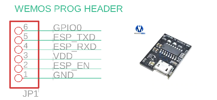
@Macca45 One good suggestion is to match the ESP-01 module pinout, because that exposes all the required pins plus a couple of extras in a 2x4 format. The advantage of using that header is many people have already made programmers specifically for the ESP-01. However, I think adding 2 more pins will make it larger than it needs to be. Normally if I’m putting a header like this is a project without USB, it’s because there’s not much space and I just want to squeeze it in somewhere.
@Rudshep I do like the idea of exposing both the 3.3V logic voltage and a higher supply voltage, like having the VIN pin on an Arduino. In fact, trying to decide on the voltage has been my #1 headache in this whole thing. There are strong and valid reasons to supply 3.3V to the board and supply the target MCU directly, and other strong and valid reasons to supply 5V so that the regulator on the target can take care of producing 3.3V.
This is one of those times there’s no right answer. I hate that 
@Tinker, @Fredderic, yes: there are already expansion headers, so I’m limiting my scope on this to being a programming header. Anything else can be separate.
Thanks @Fredderic for thinking through the layout options! I’m currently leaning towards both a 1x6 and a 2x3 option, and I’ve started documenting it here:
However, that page is still very much a draft and I’m seriously thinking about re-ordering the 1x6 version to make the pin numbers match the 2x3 version.
The logic is that the 2x3 version already exists on Espressif’s “official” programmer, so they have a defined pin assignment. There are good reasons to use a different assignment for 1x6 such as to match the wESP32 programmer or the ESProg programmer, but then the pin numbers won’t match between 1x6 and 2x3.
What I’d really like is a table that simply lists pins 1-6, and what they are, and have it exactly the same between 1x6 and 2x3. There’s likely to be less confusion then.
So my current thinking is leaning towards matching Espressif’s pin assignments, and just unrolling it to 1x6 format.
@DVanditmars Oooh, you mentioned JTAG, and I want to get onto that too! There’s already an official Espressif JTAG interface, so the format for that is set and there’s nothing really to debate about it. But it’s not very well known, so after I’ve sorted out the programmer header I want to make a JTAG board as well.
I would say the 3V/5V/Vin issue should be one of principle. The board is responsible for its own voltage regulation. 1.2V boards could happen and 5V ain’t dying any time soon. If the programming header is to be “standard” then one can’t be constrained by the board requirements. Same goes for logic levels… all pins should be 5V tolerant and be “self defending”. Design for kids… because we have a lot of kids playing with this stuff. Vin gets my vote.
If the manufacturer can’t meet the standard directly on-board then the manufacturer should supply an adapter. Makers unite! 
I’m all for a hardware standard but it is inevitable that the header is going to disappear completely if chips are factory programmed. Also, speaking of kids, nobody should be potentially exposed to mains voltages for programming purposes - ever. Who here admits to …almost… connecting a programming header with the mains still on? I do. Should we therefor not lobby for an Open OTA standard too? Maybe open a parallel thread for that? OXOTA Open eXtensions Over The Air.
Rudie
1 Like
If it was a general purpose programming header for many types of processor, I’d agree regarding the voltage. However, in this case it’ll only ever be for Espressif MCUs because it’s intended to work around the weird bootstrapping pin requirements for their processors.
If it was going to be a general purpose header, I’d only expose RESET and make the target board responsible for managing things like the bootstrapping mode. In this case though we’re trying to work around the limitation that we have to manage GPIO0 externally, so this header won’t ever be used on a non-Espressif processor.
That means we can be more specific about the target voltage, because the target system always runs at 3.3V and requires 3.3V I/O.
1 Like
I’ll read the requirement properly next time 
Just saw the draft and it makes perfect sense - and there was a surprise easter egg for me in there! For my own “peripherals” I started using the standard “servo” pin-out Gnd-Vcc-Signal and that now beautifully maps onto Gnd-3v-Tx. It means I can plug some kind of sensor or actuator into the first 3 pins where Tx is a half-duplex pin. 4 pins is full duplex. 5 pins adds a flow control. 6 pins is a full peripheral interface with system-wide reset.
Before I get flak for bastardizing a programming port for peripherals again, let me just say it is useful to me and I am thankful it is there. #HappyAccident
What I also like about the new convention is it makes a great “intermediate” standard. Own an old Sonoff TH and a Shelly 1 and a brand new Sonoff with Ox header - and a USBASP programmer? No problem… little adapter boards…
USBASP -> Ox2ASP | Ox2TH -> TH
USBASP -> Ox2ASP | Ox2Shelly | Shelly1
USBASP -> Ox2ASP | Sonox 1
Looking forward to seeing the header everywhere!
Rudie
For a standard programming header, it has to be lowest common denominator. Which means that VDD has to be 3.3V, since there’s no guarantee that there’s a 5V rail (Vin might be 12V), or even a voltage regulator onboard, e.g. when battery-powered or like Sonoff. You only need something other than 3.3V for debugging, in which case you can have a separate header depending on your configuration.
One the subject of debugging, I like the idea that GND, TX, RX should be adjacent so that you can use a reduced header, like the 1x6 esp-prog layout. This could also be achieved in the 2x3 layout.
I don’t think it’s mandatory for the 2x3 and 1x6 layouts to have the same pin assignments, although it make it trivial to have a simple SIL to IDC adapter.