After some troubleshooting I found out that the ground pins are not working. (the are connected to each other but not to the pins connected to the Arduino)
So I checked the design files to see if its my fault. But the design files are missing. https://github.com/freetronics/IOBR
Can you please check the design and if they are correct tell me which of the ground pins is used?
PS
Also It would be better to have 2 connectors instead of 3.
Pin 10 and above are useless when using ethernet. But can be used with your relay shield.
Pin 0 and 1 are not that easy to use.
Connector 1: D2-D9
Connector 2: A0-A5 (optional with D0/D1)
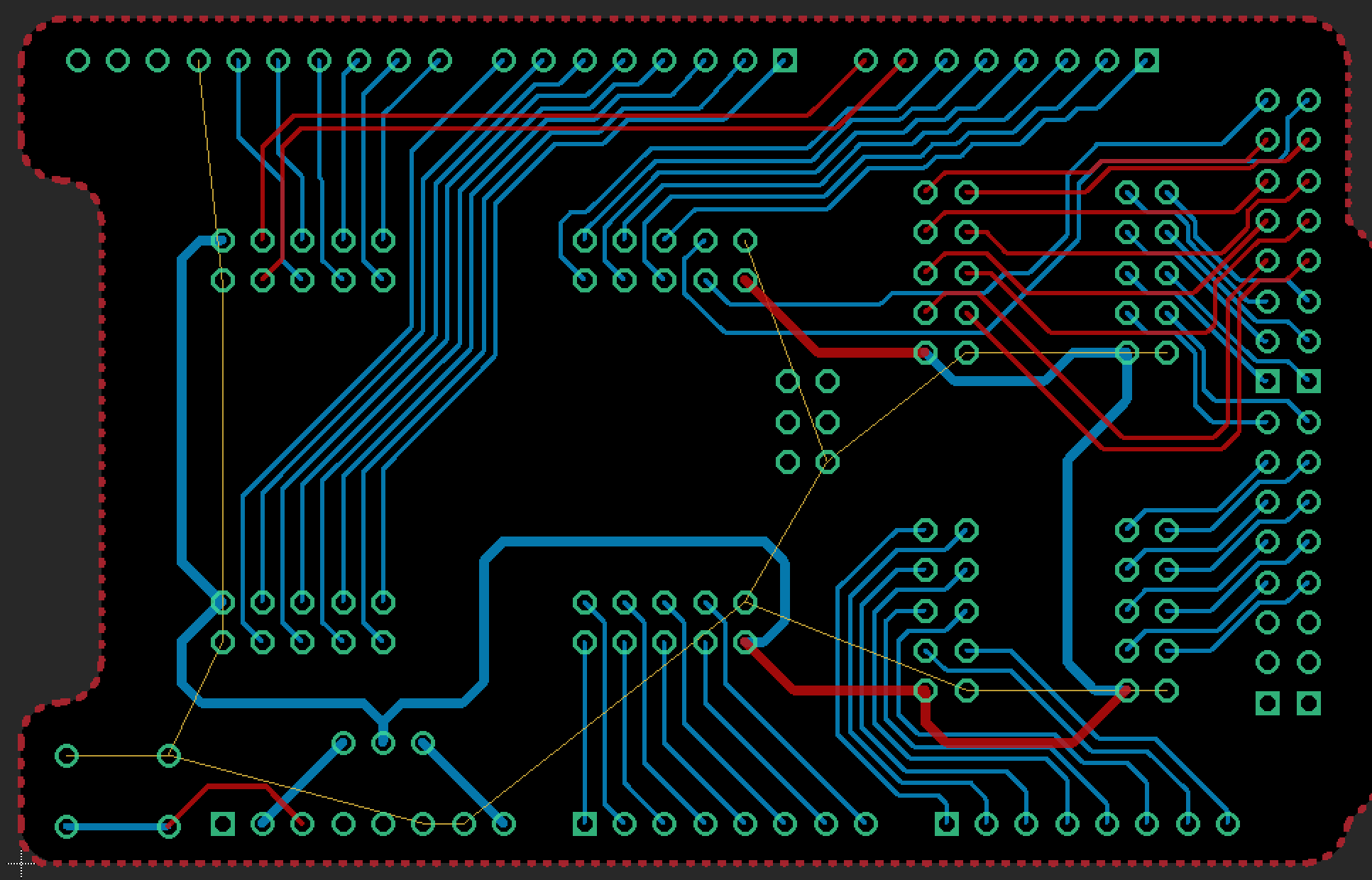
Since the original design file is still not availible i checked the “Mega” version.
we have the top and bottom lines (Red and blue)
but the thin yellow line (i changed the color) is called “unrouted” this didn’t sound good to me. however i never designed a board so it could be that i misunderstand it.
is there someone using this boards? Or can someone explain the unrouted part?
if the uno shield is the same as the mega shield then it would mean that i managed to solder all pins correctly except all gnd pins.
Hi Mark For some reason you are looking at the old 10 pin file. I am using the newer 12 pin versions of this board. I dont think you can trust that layout as accurate
The current versions of both the Uno and Mega format are in the SuperHouse GitHub account, but the pages for those boards link to the Freetronics account. I pushed the first version of the IOBRMEGA to the wrong GitHub account, then pushed both the designs to the correct account but didn’t clean up the links.
I’m going to delete the misleading IOBRMEGA repo (with the 10-pin headers) now, and fix the links. For the record, this is where the correct files live:
Sorry!
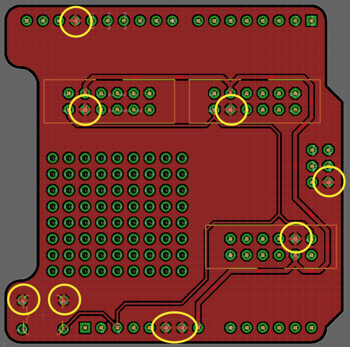
Regarding the red unrouted wires showing in the design, those are ground connections that go directly to GND polygons that cover the entire top and bottom of the PCB. If you open the design in Eagle, then click the “Ratsnest” button, it will pour the polygons and all the airwires disappear.
I’ve checked the ground connections on the current version of the IOBR, and it looks ok. I’ve attached a pic of the top layer of the board (everything else turned off) with the ground polygon poured, and the ground connections circled in yellow. You can see that each of the connections has a little cross where it links to the polygon, so it’s possible to visually confirm that all those pins are linked together on the top layer. They’re also linked on the bottom layer.
After checking the picture above i checked al pins again and i noticed that i wrongly soldered 4 pins. with 3 of them where ground.
i soldered them again and they are working perfect. so apology for not checking my work correctly.
Great that you updated the links to the files.
please consider the “PS” when you ever make a new version.
at my second lightswitch project i used the screw terminal shield instead of this board since that one allow me to use the correct data-pins.
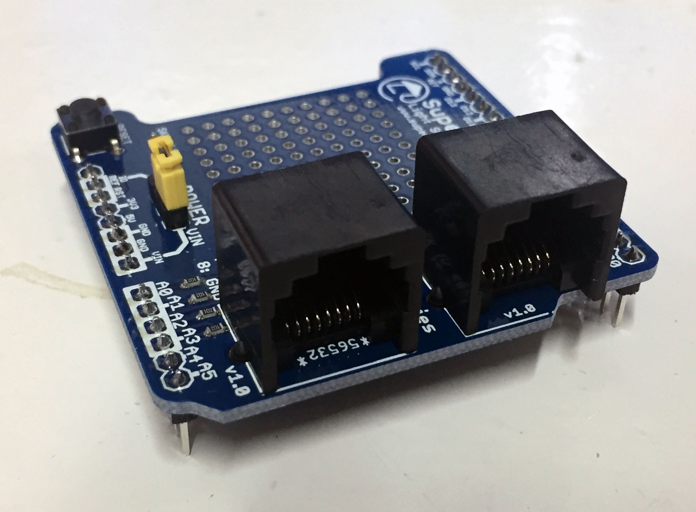
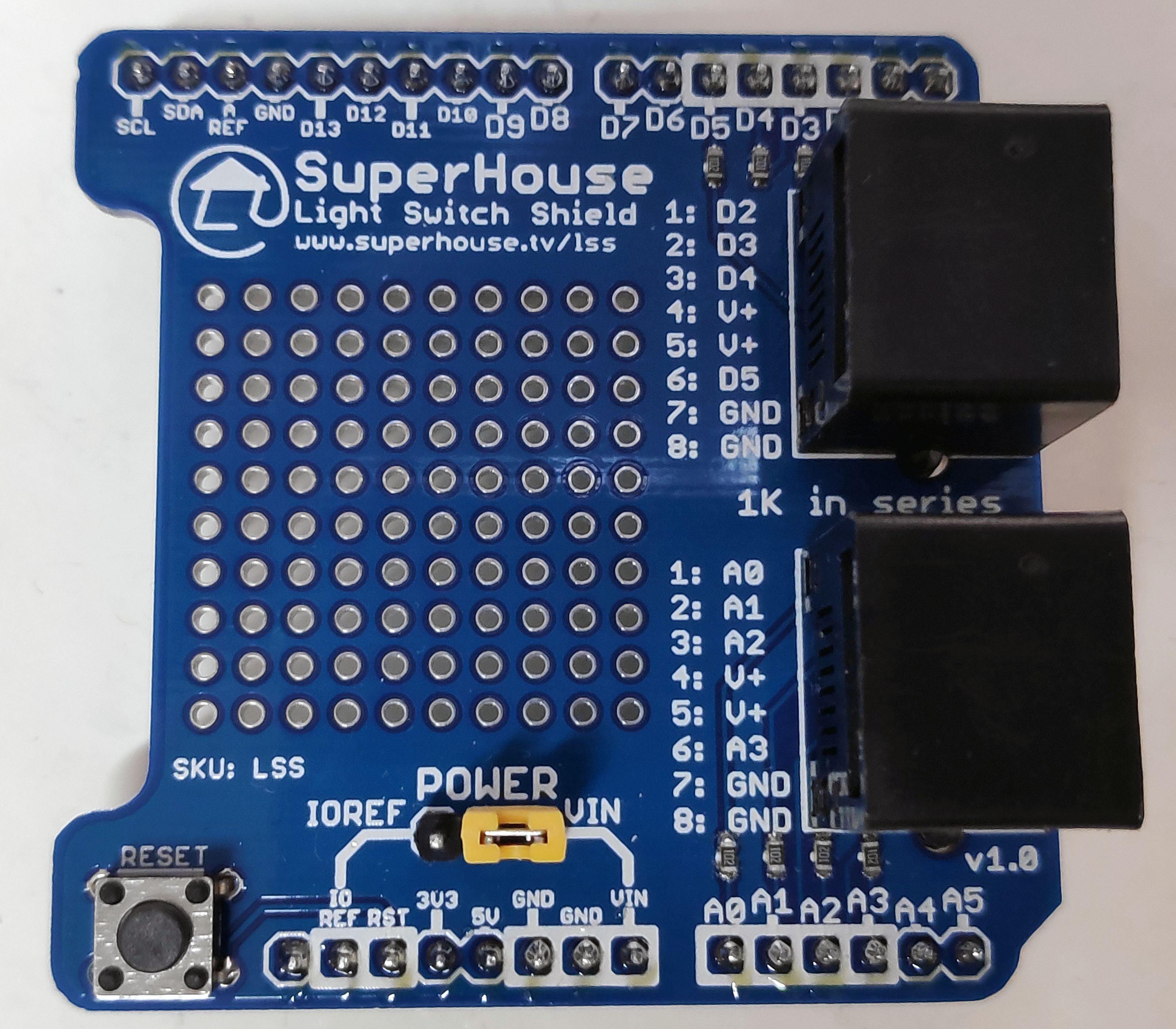
Maybe this will be useful for you: last year I started designing a shield to connect custom-made button boxes for wheelchairs to an Arduino, and while I was working on it I realised that electrically the wheelchair buttonbox and a light switch is exactly the same. I adjusted the design to make it useful as a simple direct connection for my light switches:
With this, I can use Cat-5 to plug a light switch straight in. No need for an I/O Breakout and then the RJ45 converter board. It only has 2 sockets on it, but that may be enough in some situations. The pinout is shown on the silkscreen: