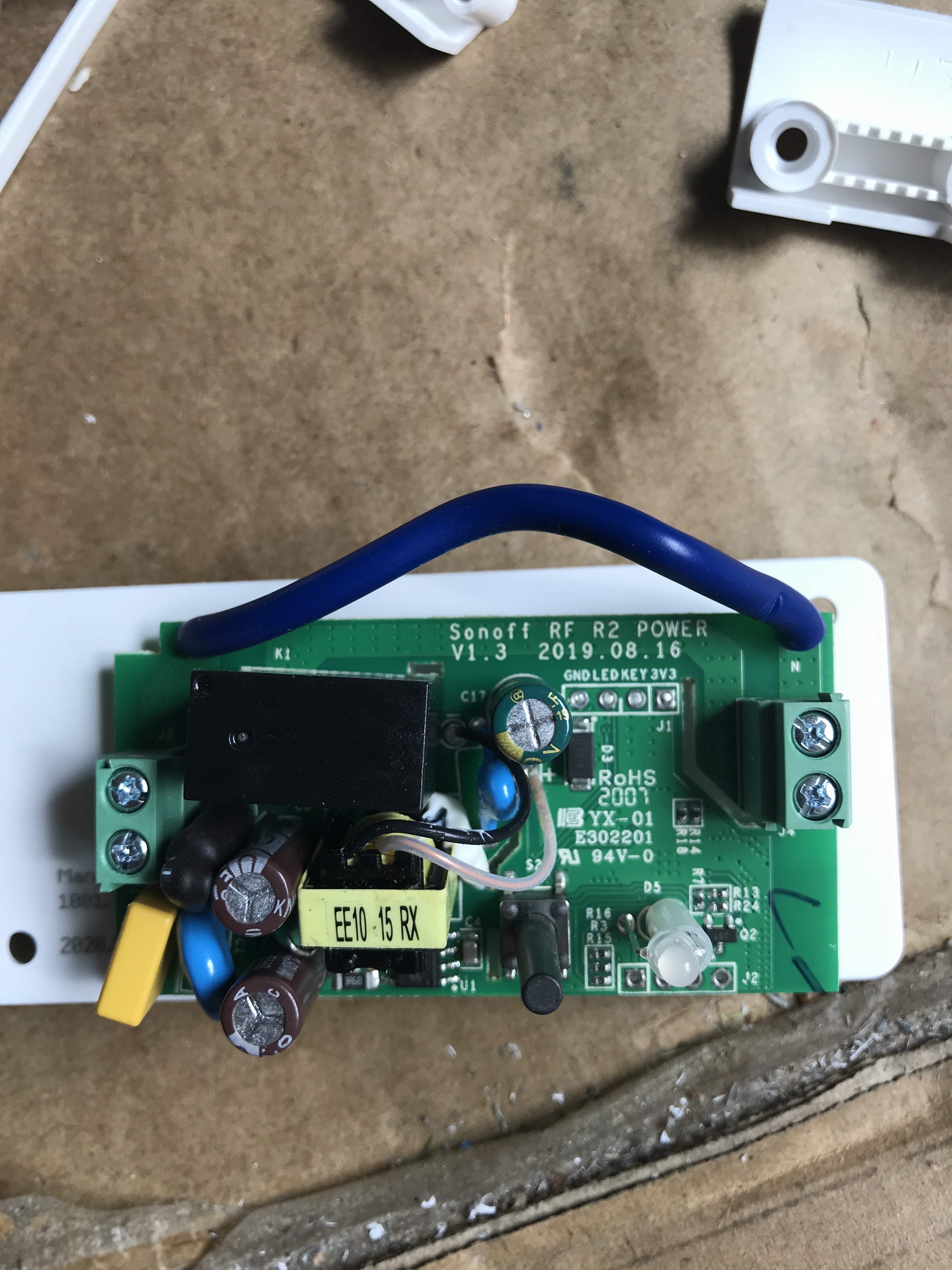
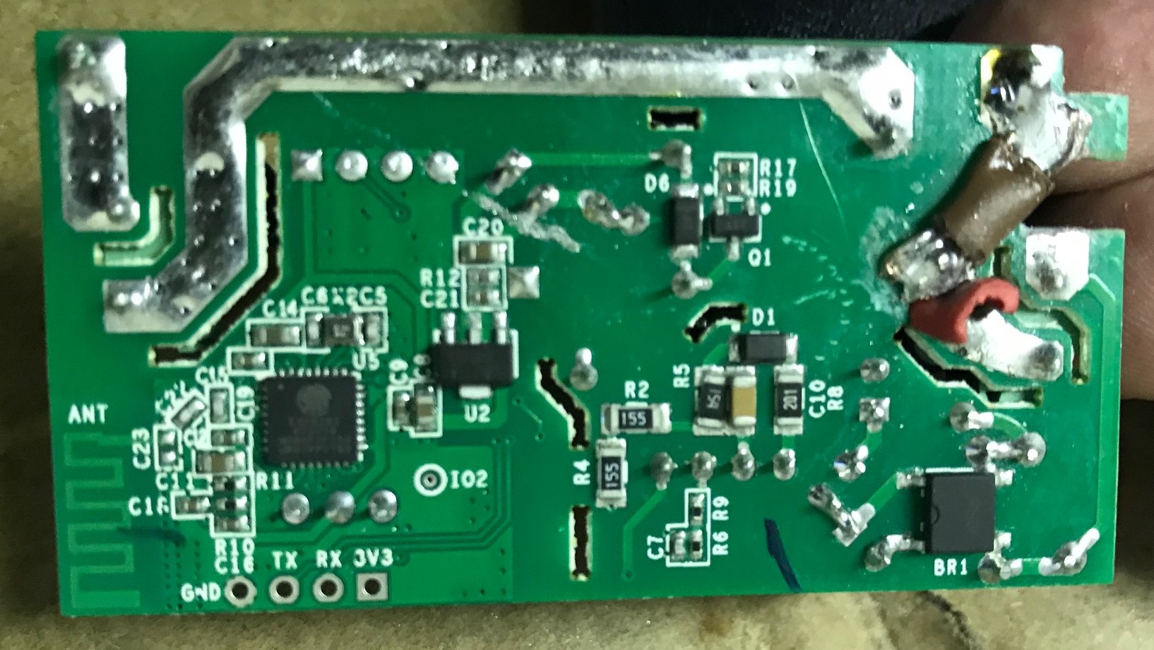
Note only 1 wire on top of board, note text on the board, note moving of ”programming pins”
Cant post backside of board beeing a newbie (sorry) in this forum
Modifying the board had me go purchase fine grinding tools for the dremel, and i had to use magnifying glass ( cause it was hard to tell if cutting the board through enough ( and not too much and running into other components )
Hi
I have received the same board last week, and could flash it, but cannot start it.
Did you find out how to start this module?
What is “key” connect to, is this a GPIO you could identify?
Thanks in advance for your help,
Felix
I never got time to flash it, i just used it out of the box and run them via google home ( ok google turn on “thing” ) so i cant answer your question… sorry
DISCLAIMER, if you are not familiar with these things you should get professional help with apropriate knowledge and all certifications so it is is lawfull in any and all countries you will use device in.
I DO NOT PROMOTE TO USE THIS VERSION OF SONOFF TO MODIFY TO WORK AS A DRY RELAY. IF YOU CAN… GET ANOTHER VERSION
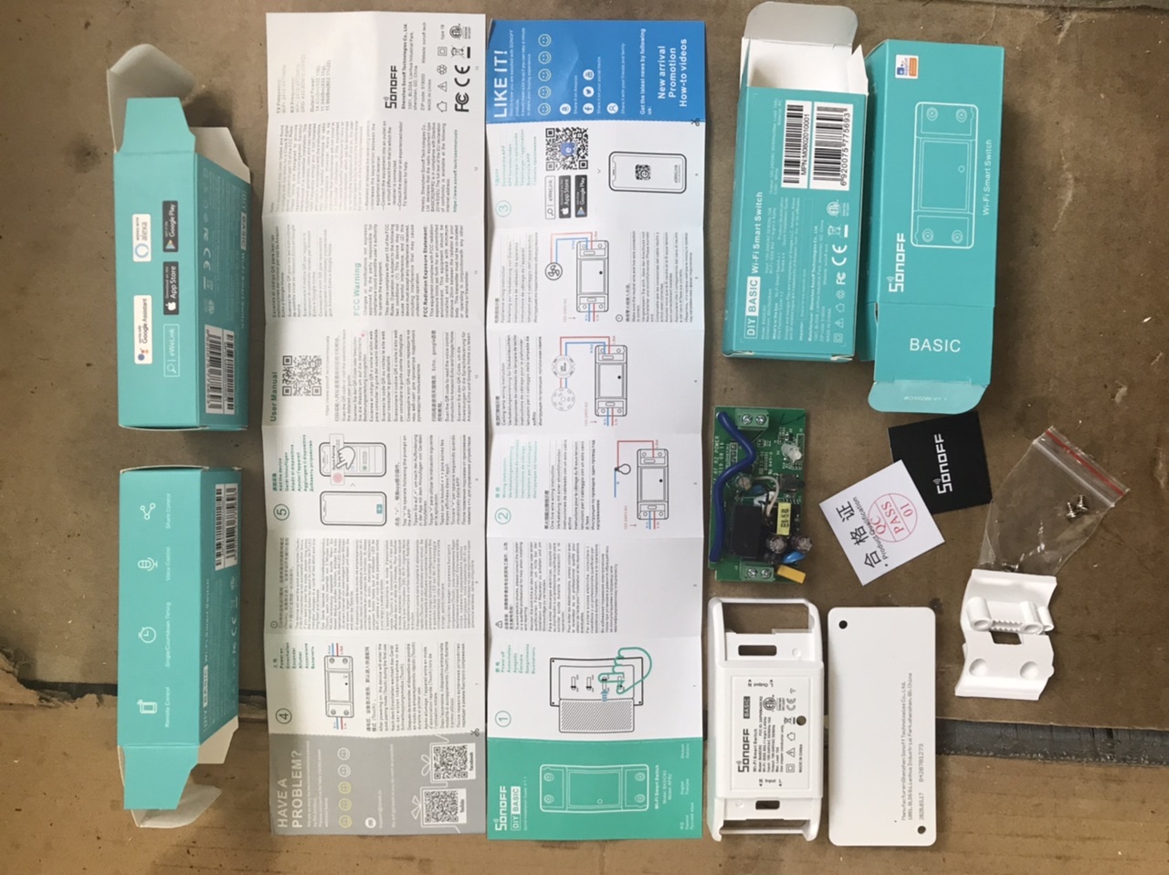
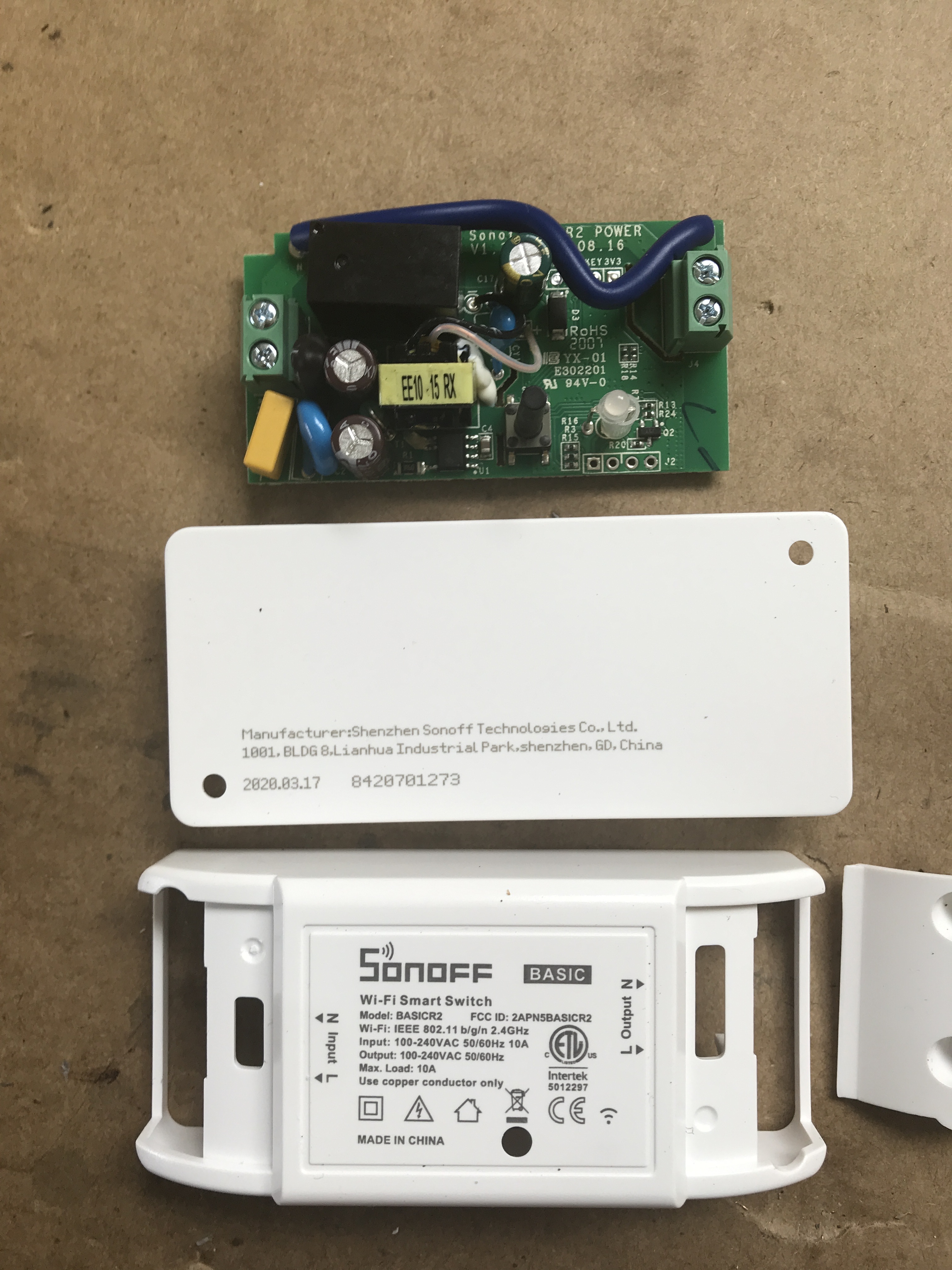
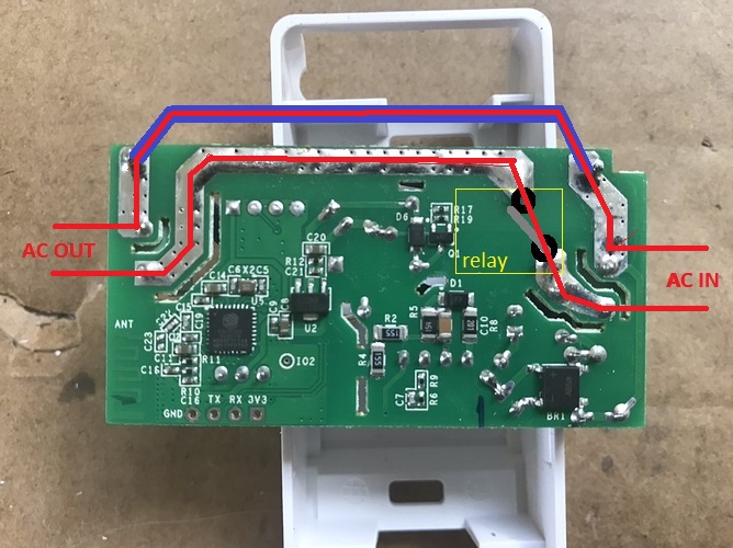
so just for reference, this is the board…
.
I have added a “blue line” in the picure above the board to symbolize the blue wire on the other side of the board; when connected to mains power and relay set to activated ( relay marked as yellow box ) you see the way the current moves from right side “AC IN” to the left side “AC OUT”.
.
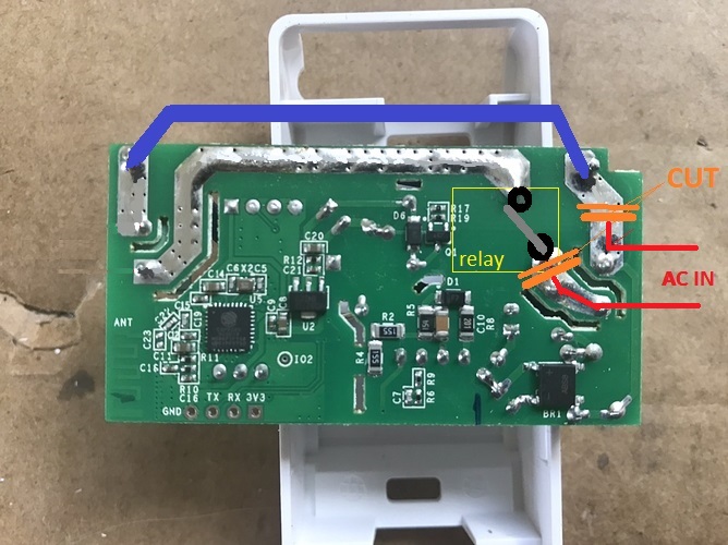
What you want to do is separate mains “AC IN” from reaching left side, hence DO THE 2 CUTS, a BIG one and a SMALL/thin one, it is really narrow between the solder point of the relay and the solder point of a fuse, and you should be very careful doing that cut ( always measure so you dont have electrical contact between the sides of youre cuttings ).
.
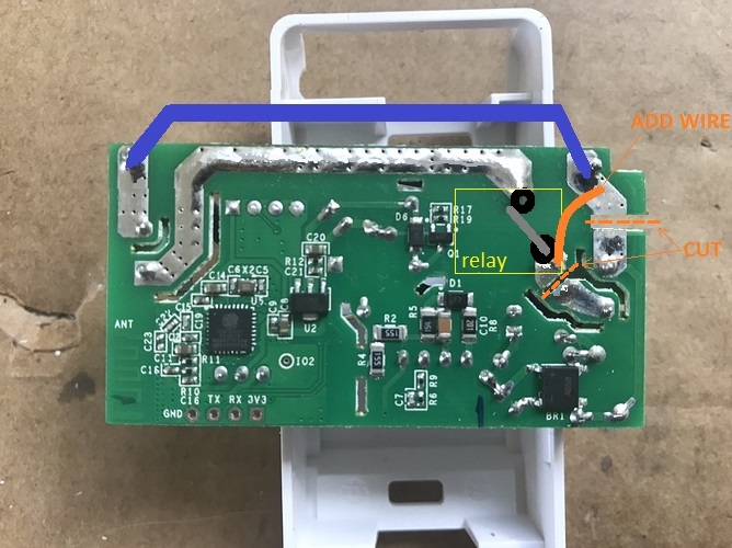
After you have done the cuts ( always measure so you dont have electrical contact between the sides of the cuttings) Add a wire ( represented by orange line ) i came to the conclusion it is easier to add that little wire then to reroute the blue wire which exist on the other side of the board, because when i tried to reroute the blue wire it interfered with the plastic case, resulting for me that the board didnt sit ok in the case.
.
with the cuts and the added wire you know see that we have made a separation to accomplish a dry relay functionality
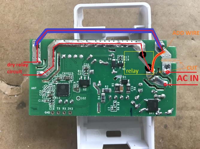
NOW … the “SMALL/thin” cut i was not very happy with. I would have liked more “air” between the two separated sides, so i added small bit of wire insulation in that SMALL/thin cut so i would not have to worry about AC current JUMPING over onto the relay.
not the most good looking soldering i have done, but you get the grasp of it, and you see where i have stuck the insulation taken from an electrial wire which i pushed in the SMALL/thin cut ( all the way through the board, but of course jammed on the components on the other side of board )
I have the same one. Was able to flash latest Tasmota on it using tasmotize on Linux and it works fine. I used an old cp2102 usb to serial(with 3.3v) connected to the 4 pins at the edge. To get into flash mode, I held the button down while connecting the usb to serial to usb port, then released it immediately before commencing flash.
I am using it as a smart relay and looking for a way to use a 3rd IO pin for a temp sensor (SPI)