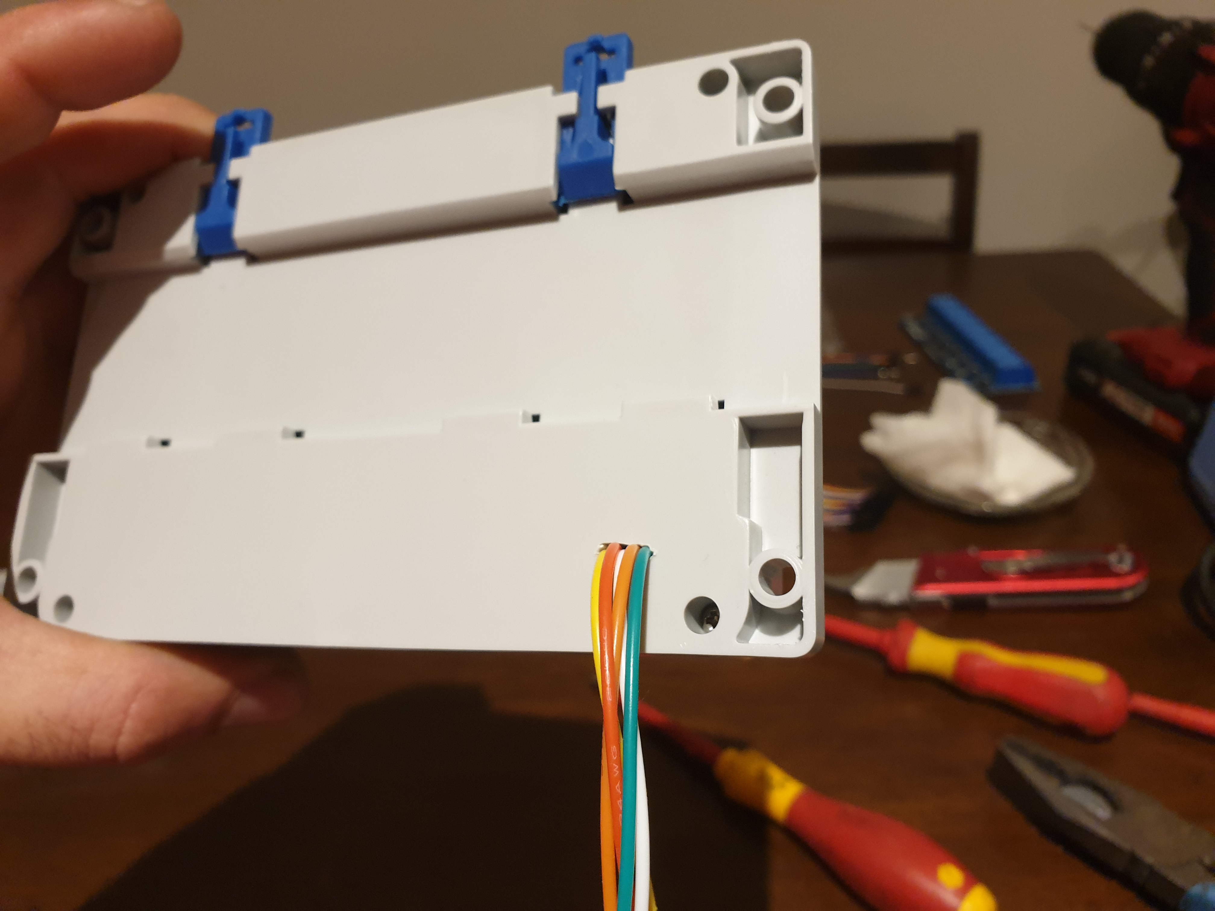
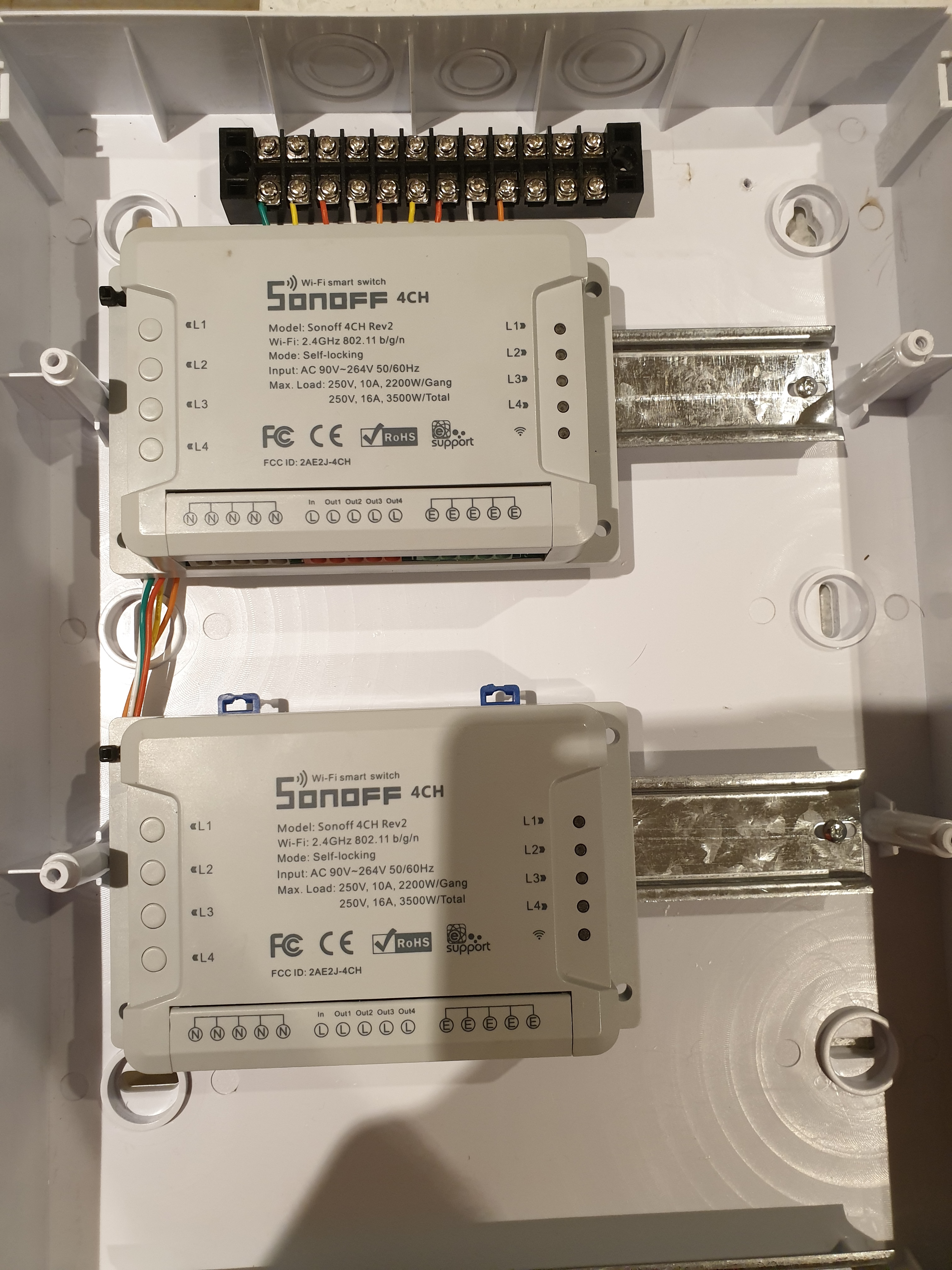
Awesome Jon, what you described on #25 from 10 minutes and on is exactly what I plan to do but with sonoff modules. I think i will use 12v over Ethernet to power the leds too and 12v relays that I will mount locally next to the sonoff 4ch modules that will have the connections from the hacked onboard channel buttons.
Your install is on another level to mine. Yours is complaint whereas I’ll be using the sonoff modules but will have a 3 pin plug to each and plugged to a gpo. Technically “not a part of the install”
I am basically going to start off as a cloud smart home and then later on employ tasmota and run the system on its own server. I have worked with cbus and dynalite as a electrician but I always employed someone to do the programming for me.
I’ll have to get my coding skills up to scratch before I move to tasmota, also can tasmota still be used with cloud services?
Yes, Tasmota can connect to a could-based MQTT broker, and it also has emulation modes so it can pretend to be a Belkin Wemo device if that helps with controlling it with a cloud service.
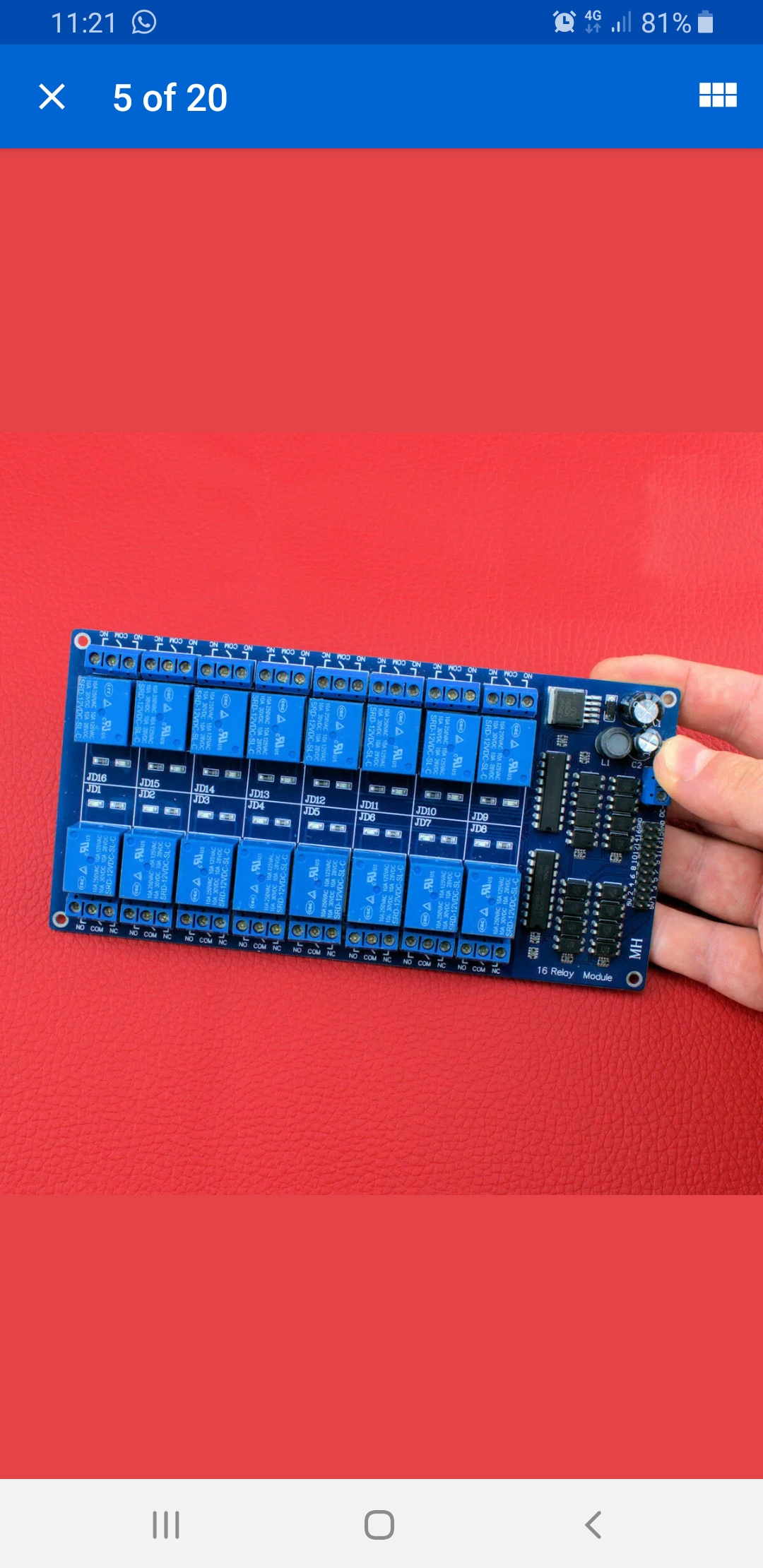
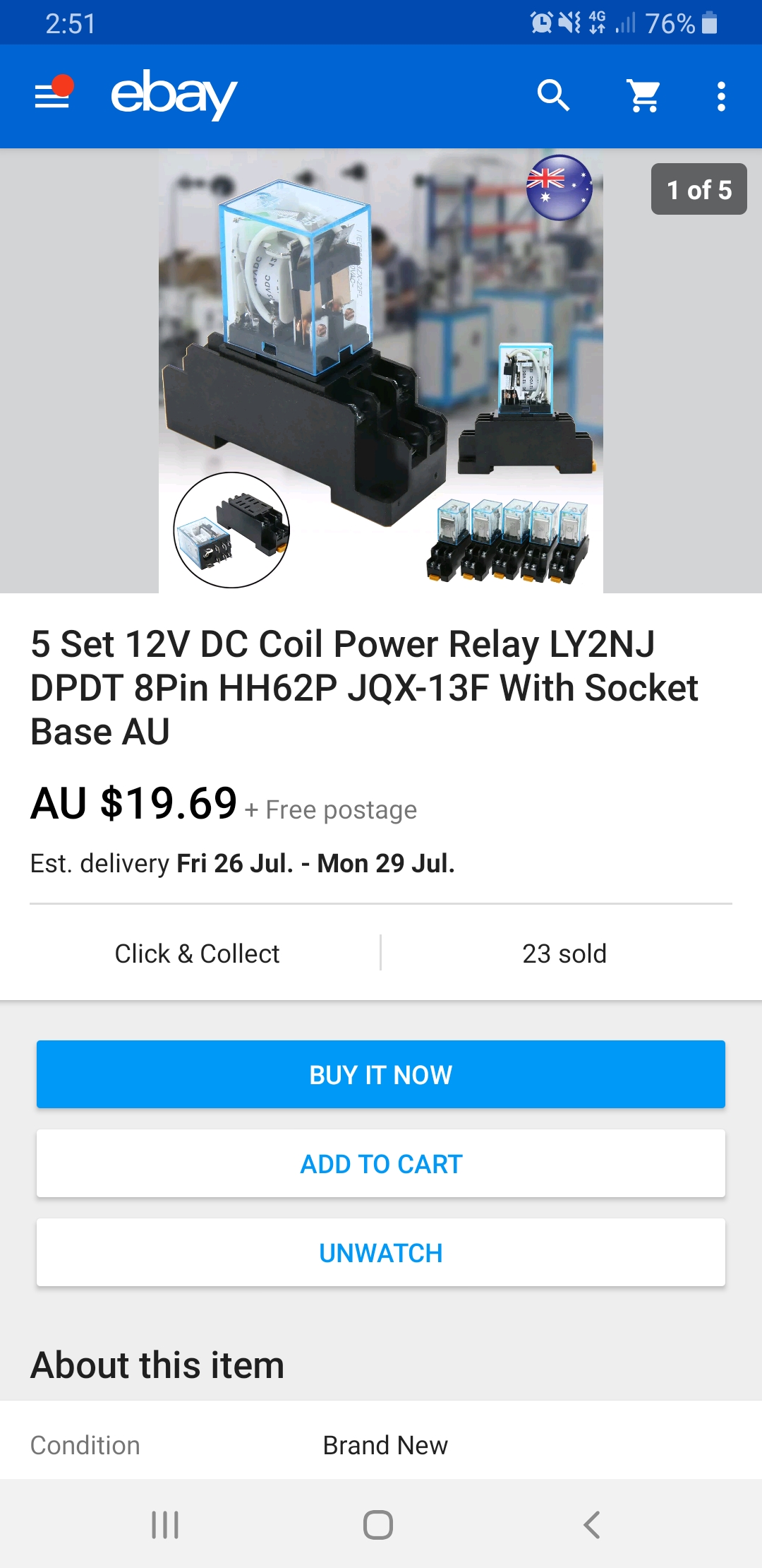
Has anyone used these type of relays before? It’s a 12v version. I just want to know if 12v is also used to trigger the channels from the header. Can’t find any info and when i messaged the “australian” seller on ebay i got the typical Chinese automated message.
Just edited this… for the 4th time… SHeesk! You feed the board with 12v on the blue terminal. The header is for 3.3-5v control as the optoisolators look like the bog standard 5v models used on pretty much every one of these boards out there. In question? Google the part number on the opto’s (little 4 legged boogers right next to the header) to know for sure but my money is on the 5v version. The rest of the crap above your finger, the caps and such, are for the coil control side of the process and is fed from the 12v input under your thumb.
Didn’t find one for the whole board. I looked up the part number on the relay… SRD-12vdc-*** which tells the story. As does the optoisolators. The rest of the hardware on the board is what creates the interface between the 5v input and the 12v control. Since these boards are designed for the Maker hobbyist, the dime a dozen models are set up to run from cheapo microprocessor boards like Arduinos and they will only output 5v.
Oh ok I figured it was a 12v powered board with 12v signal switch on the headers and contacts were dry. That’s what I’m actually after. Seems like this won’t be any good for me then
So I ordered one to play around with… only a 4ch however I can achieve what I set out to do with it. The vcc is 12v supplied gnd is for the relay coil. In1,2,3,4 are switched via negative or gnd from suplly, in this test case, the battery. What I plan to do is cut the track where shown so I can use the relay as dry contacts. Now for the switches on the wall I’ll have have the negative switched instead of the positive. Simple and much cheaper than the other options:ok_hand:
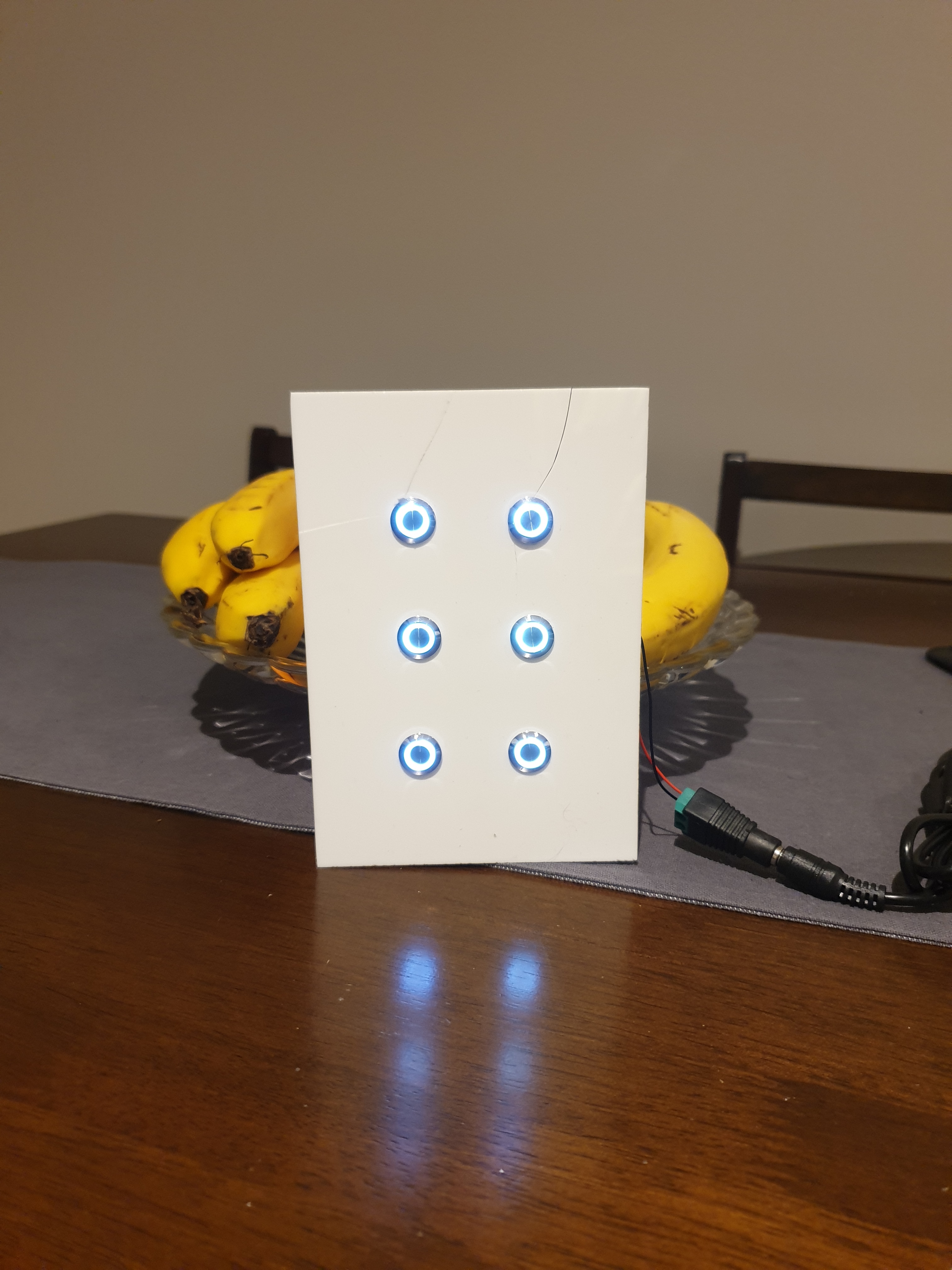
Made a switch plate tonight cause I was excited when my switches came in… 2mm white perspex and 12v momentary push buttons. You can see the cracked perspex cause I drilled them out by a hand drill… I’ll be using a drill press next time or might go the laser cutter route.