As sonoff 4ch, basic etc doesn’t have option for external switch like the”th” models. Do you think it’s possible to hack the onboard switch and have a let’s say a 15m run to a custom made switch panel using cat5? I want to mount 2 4ch sonoff modules in a enclosure and have 2 wall switches controlling them from another room. Do you think it’s possible? Will it trigger the channels or is it too long of a cable run?
Welcome to the group @Michael
I do believe that it is in theory possible. I looked at the Belkin spec’s for their CAT5 cable and it shows that it has about 15 Ohms resistance for 100 feet. So, unless my pathetic math skills fail me, which they usually always do,  You should still be okay. I did not do any of the research on how low the trigger threshold would be for the chip on the Sonoff but I don’t believe you are in questionable territory for a simple button.
The real question would be… what would the situation be where you would need a hard wired remote button? The Sonoff is a wireless device and there are many ways to control it either through the Sonoff software or, once reflashed with Tasmota, through MANY other avenues. All of which beat an analog push button approach IMO. Once installed, they are pretty much a “set and forget it” device. Unless you are trying to keep from adding some sort of smart switching device in the room you are running the CAT5 to, (actual smart switch, phone/tablet with a GUI of some sort, etc…) there is really no need for wired switches.
Hi Guru and thank you for your reply. My means of switching is because of my mother because she still lives with me, I am actually building a house soon and I am the electrician. She is not tech savvy and I’m trying to keep it as simple as possible for her.
The reason why I would like to hack the 4ch on board sw’s is because in the living room/kitchen/alfresco I require 2 6gang sw plates so I will be using 6channels. 2 plates because 2 way.
As for what resistance the sonoff would trigger, that is a great question, I neither have tested as my gear is on its way. I have also purchased headers etc to flash tasmota. However I did plan on running 2 cat5 cables and double them up to reduce resistance.
For my type of application, how else could you go about it other than what I plan to do and still keeping the channel state true.
Thank you
You could put sonoffs (flashed with Tasmota) in the locations you want the push buttons & configure them to trigger the ones that are actually controlling the lights (or whatever).
Basically use wifi as the connection & sonoffs as a switch.
Or… If you’re feeling particularly adventurous, Build up your choice of ESP8266 module with pushbuttons, batteries & Tasmota into standalone remote controls for the sonoffs.
I have something similar in the queue of projects. Unfortunately, not fully fleshed out yet. But Tasmota does support this…
Wheew…yeah, the options are pretty much endless as to how it can be done but it really depends on how technical you want it to get. I seriously doubt you would have an issue with even a single pair of CAT5e wires for the switching but doubling them would obviously help. If you are looking to do a truly smart home, then wiring to the switches on a Sonoff kind of defeats the purpose for the Sonoff in the first place. There are other devices like Shelly 1’s that are designed to go into switch boxes and act as a gateway controller like a Sonoff and you can still use the switches in the box as well. So… I guess, how ‘smart’ are you looking to make your home?
You’ve actually given me a idea… since the custom made 6gang switches need 12v for the backlit led, I may just make use of some 12v car relays I have laying around that can wire to trigger the onboard sonoff switch. Still means I’ll have to hack the module but that’s ok. I can make a neat little bus bar connector to join wires.
I totally understand when you say if defeats the purpose… but I’m just trying to cover all basis
I get that. Nothing wrong with doing it that way if it meets the need. Just not the original intent of the product… but as we see in this type of thing all the time, it’s what you make possible with it that is important. I (mis)use products all the time 
Thanks mate.
I guess to add to this discussion. When my modules arrive I will test with a potentiometer as to see what the highest resistance the module accepts to trigger the channel
1 Like
I’m pretty sure you won’t have any reliability problems with Cat-5 cable doing it that way: the resistance won’t be a problem, the potential danger is that having a long wire like that attached to an input pin on the ESP8266 could cause damage to the chip if there’s a big lightning strike nearby, for example.
That said, I still don’t think you’ll have a problem. What you describe is very similar to how my house is set up. Every light switch is just buttons on the end of a Cat-5 cable, wired back to central light switch controllers. I actually put a 1k resistor in series with the wire to each button to act as a current limiter if there is voltage induced on the wire. There’s more info about my switch setup in these videos:
2 Likes
Awesome Jon, what you described on #25 from 10 minutes and on is exactly what I plan to do but with sonoff modules. I think i will use 12v over Ethernet to power the leds too and 12v relays that I will mount locally next to the sonoff 4ch modules that will have the connections from the hacked onboard channel buttons.
Your install is on another level to mine. Yours is complaint whereas I’ll be using the sonoff modules but will have a 3 pin plug to each and plugged to a gpo. Technically “not a part of the install”
I am basically going to start off as a cloud smart home and then later on employ tasmota and run the system on its own server. I have worked with cbus and dynalite as a electrician but I always employed someone to do the programming for me.
I’ll have to get my coding skills up to scratch before I move to tasmota, also can tasmota still be used with cloud services?
Yes, Tasmota can connect to a could-based MQTT broker, and it also has emulation modes so it can pretend to be a Belkin Wemo device if that helps with controlling it with a cloud service.
Awsome! good to know! Geez these modules take their time coming from china
Just finished my test and 1.1k ohm switches the channel just fine. Value was maxed out on my potentiometer.
1 Like
Perfect. Means you can run the distance you need and not worry about it working properly.
Yep! But I am going to go the relay route and 12v POE
I just tested them in case some one else could use the info.
Has anyone used these type of relays before? It’s a 12v version. I just want to know if 12v is also used to trigger the channels from the header. Can’t find any info and when i messaged the “australian” seller on ebay i got the typical Chinese automated message.
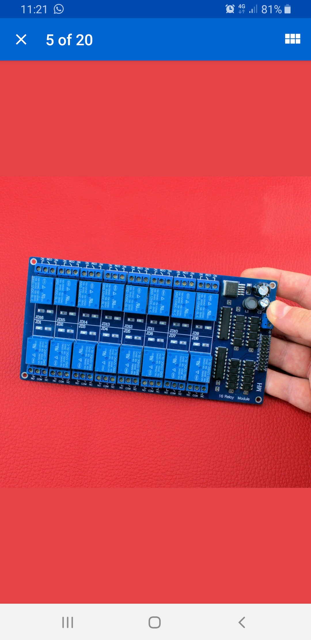
Just edited this… for the 4th time… SHeesk! You feed the board with 12v on the blue terminal. The header is for 3.3-5v control as the optoisolators look like the bog standard 5v models used on pretty much every one of these boards out there. In question? Google the part number on the opto’s (little 4 legged boogers right next to the header) to know for sure but my money is on the 5v version. The rest of the crap above your finger, the caps and such, are for the coil control side of the process and is fed from the 12v input under your thumb.
1 Like
Good to know! I plan on using one to trigger the channels on the 2x 4ch sonoff modules I have.
Guru, may i ask how/where you found a data sheet for it
Didn’t find one for the whole board. I looked up the part number on the relay… SRD-12vdc-*** which tells the story. As does the optoisolators. The rest of the hardware on the board is what creates the interface between the 5v input and the 12v control. Since these boards are designed for the Maker hobbyist, the dime a dozen models are set up to run from cheapo microprocessor boards like Arduinos and they will only output 5v.