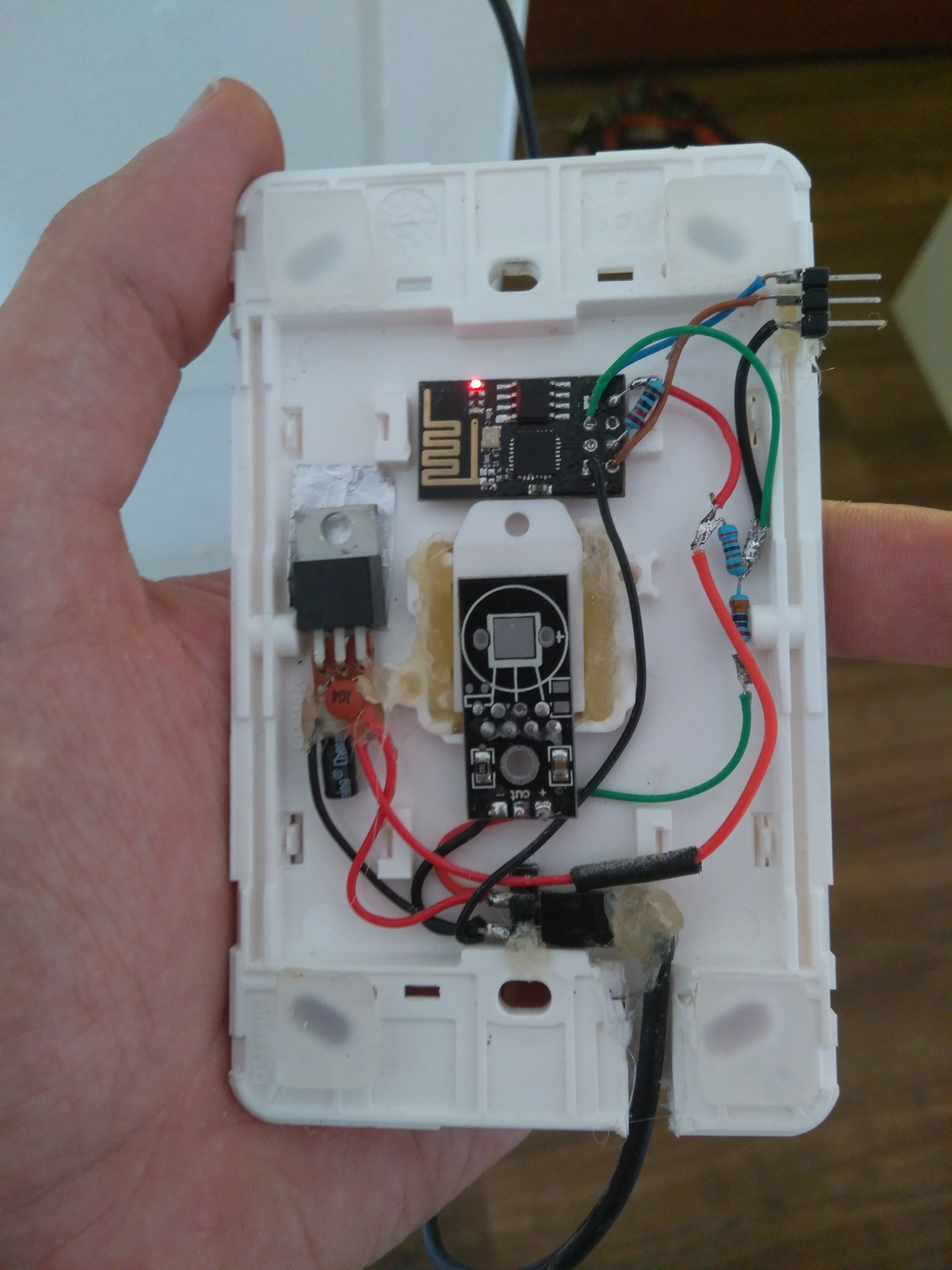
I recently mounted a DHT22 in a wall mount light switch to make it a little less intrusive.
It looks ok and performs good at the high end of the daily temperature spectrum, but when it cools down past 27°c it reads the same results.
I think the components (ESP-01 and a LD1117v33) that are in the housing may be affecting it even though they are 10mm away and insulated with hot glue and plastic.
When i place a fan on it the readings become more accurate. This was more of a trial for a future plan of having a sensor hub with multiple sensors, possibly in the ceiling.
I am starting to think I may need to have a better-insulated sensor and possibly a mechanical air flow to pull some of the ambient air in.
Have any of you guys had success with this sort of setup?
I would think, though I don’t know for sure, that the sensor itself really needs to be isolated from the hardware that is reading from it. I assume you are correct in thinking that the components in the box are putting out just enough heat to mess with the readings. I can’t see it being much but it doesn’t look like there is any way for the air flow to get through the sensor, just against it. The wall materials will retain ambient heat and throw off the readings as well.
Yes, I’m pretty sure @Guru_Of_Nothing is correct, you’re seeing heating from the other parts. You could test this by running the sensor separated from the rest of the parts by maybe 20cm of wire so the only thermal link is via the wire, and see if the lower end response is better.
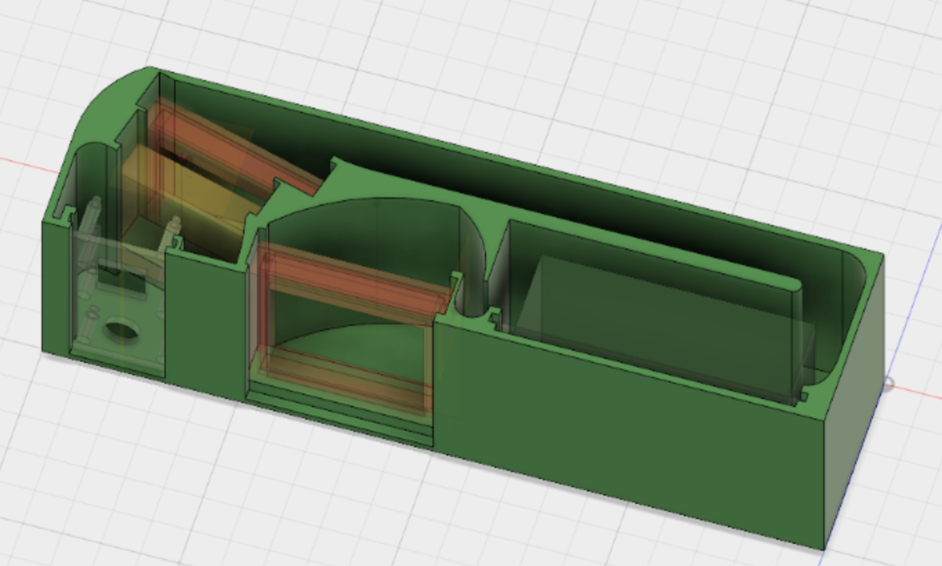
I’ve been working on a new project specifically to do this sort of thing. I’ve recorded part of the first video about it already. In my design I’ve mechanically isolated the sensor from the rest of the parts on the same PCB by adding a slot to the board, removing the ground plane to prevent thermal transfer, and necking-down the PCB at the end of the slot. I’m also relying on convection airflow through the housing, with the sensor at the bottom and all other parts above so that air will flow up past the sensor first before the air is warmed by the other parts.
Yip you guys are spot on, I done some testing and recorded the data to my SQL server last night and there was a clear decoupling of the data between two sensors at about the 27º mark at 3am.
I am thinking I may move the LD1117 higher in the housing to allow the component heat to rise.
If that fails I may connect the ESP-01 GPIO16 to the reset and deep sleep the ESP between reading as its unlikely the <2s boot will raise the temps, and the low current draw “should” should be enough to keep the LD1117 and the ESP cool.
Unfortunately, that just means more firmware editing (to an already complicated program) lol and the daring trick of soldering the esp-01 GPIO16, it’s so freaking tiny, I don’t think I have a wire small enough not to dwarf it.
I’ve found the exact same problem with the Sonoff modules. I’ll add a DHT22 and stick it on the side, but the sonoff radiates too much heat. And I get a ~20 degree F increase in temperature when the relay is engaged due to heating in the coil.
That is definitely an issue, especially if you are using the data to perform an action.
Last night I took to CAD and redesign a solution that uses a 25x25x7mm 5v fan, it makes things a little more complex as once you start forcing air you are dealing with increased dust particle count, I have ordered some filters and will make an acrylic housing 30x30x50mm long and should fit everything in there with the added benefit of the fan cooling the ESP and voltage regulator after it has passed through the DHT22.
I am redesigning my firmware also, so it deep sleeps between reading cycles, the biggest pain is we turn off our wifi at night so I have the esp logging the data through the night and then it dumps it to the SQL DB in the morning, pretty sure the sleep allocated memory will not be large enough for this
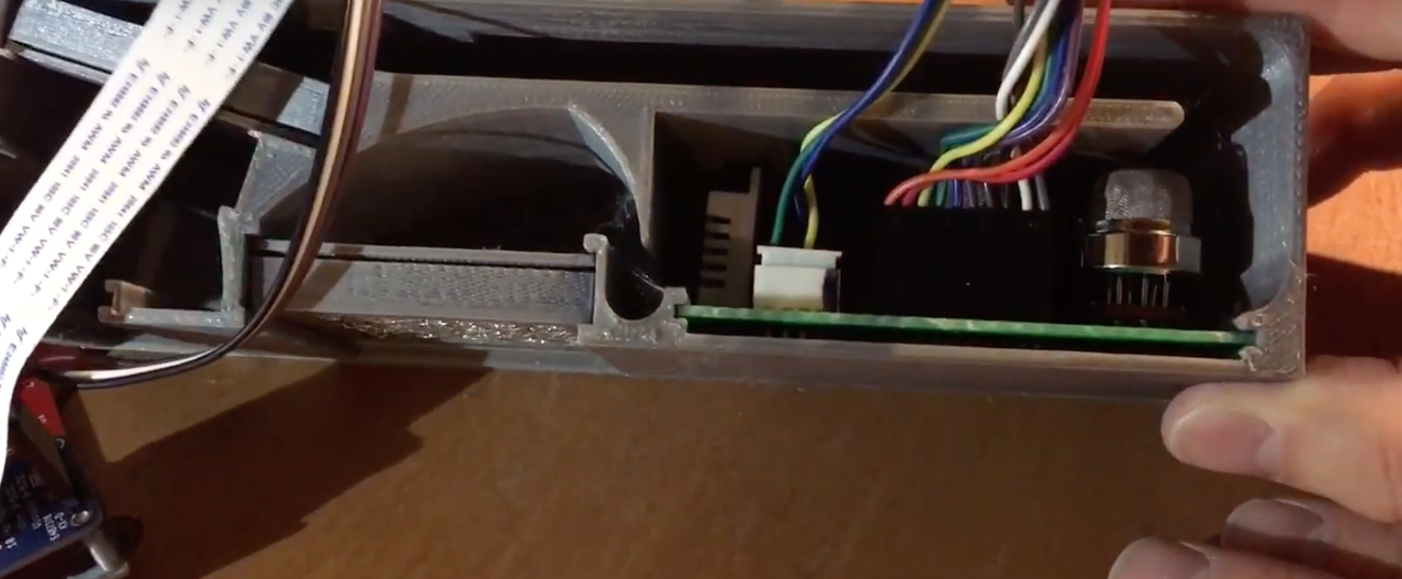
I created a sensor array for a smart range hood about a year ago that used a DHT22 temperature/humidity sensor (among 5 other sensors) to control the vent fan. The DHT22 was placed in close proximity to some “MQ” sensors like this which require to be continually heated. For this and many other reasons, I incorporated a fan to circulate air through a custom duct assembly and put the temperature sensor front and center.
Baffle design in Fusion 360:
So a few weeks ago I got a load more esp-01 chips for various iot devices around the place.
As I had a few spare I thought I would attempt soldering the gpio16 from the chip to the reset pin.
With some shaky hands I pulled it off and proceeded to flash a new peace of firmware that I am developing for the esp8266 that is more universal than say tasmota, as I still like to write sketches but it’s nice sometimes to update variables without flashing so I have been working on a web server that for the esp that covers most basic operations and also has a App sketch for utilizing the specific functions for that device.
So once I got this setup with some basic deepsleep operations I done some testing and what do you know, due to the massive decrease in current when sleeping the enclosure maintains general ambient temperature. By the time the esp draws enough to warm the regulator it has already taken the samples, processed them and transmitted them. The whole operation only takes about 15sec with a 1000ms between samples.
Pretty happy with the results, next challenge with the firmware is modification to suit my watertank sensor that only takes a sample every 12 hours, deepsleep can only be maintained for 70min at a time on the esp8266 so I am going to use eeprom and a start function to basically run before anything and nocks it back into deepsleep till the required time is achieved.
Pretty fun getting accustomed to c++ but I am still hitting the odd road block lol
This is very interesting. I normally use K7803 regulators because they’re switchmode and generate less heat, but in this case a linear regulator may work out better because it can drop to extremely low power while maintaining the output voltage.
It would be interesting to compare swtchmode and linear regulators when driving an ESP8266 in sleep mode. I have a feeling that linear may be better!
Yes definitely interesting to compare them, I also looked into the K7803 for projects under constant load as the efficiency seems to be the best on them. I have used a few of them cheap mini buck converters and they seem not to bad and the package is almost smaller as the LD1117 with a couple of balancing caps.
Energy loss from 5v to 3.3v is bearable but not great when dealing with temps, I have really grown to like the ESP8266 (after getting the perfect flashing recipe down). Its only downside is running at 3.3v and if running alongside 5v components you are always ending up dealing with the additional voltage on inputs, end up using more resistors than I would like.