Hi everybody.
I’m busy putting together my home automation project and want to take on a particular set of challenges… These are my (lofty) design goals…
- A node cost of under US$5 per switch point so every single light switch in the house can affordably be automated. “Cheap” smart switches currently go for US$15 - $50. Sonoff Basic is around $5 now but does not meet the rest of my requirements.
- Wired for maximum reliability and a 20 year life span.
- Switches and sockets in the house keep on working in manual mode even if the home automation and even the module is completely dead. As if HA wasn’t even there.
- Separate high voltage from low voltage to conform with building codes.
- Installable during construction by a “normal” electrician.
- Upgradable without having to touch the mains wiring after certification.
- Safety first (or 7th in this case).
There are basically 3 architectures I like, each with their own pros and cons.
A. Jon’s way… KISS… Simple button with low voltage from wall switch to central cabinet, central relays to switch high voltage. Hub-and-spoke.
B. Professor_Alex… CAN module in the switch and relays in the central cabinet. Bus/Flattened Star.
C. MrFixIt1952… 3 and 4 way switches with a terminating relay. Traditional, P.I.T.A. but follows code and will still work decades from now.
So, how to combine the best of all 3? Not entirely sure yet but here’s a start…
The first problem I want to solve is how to make a module that can live inside the switch box (behind the switch) and be remotely controlled - but will still work if there is no smartness in the smart home. Basically a relay in parallel with the light switch. That will let me switch the light on and off with the switch as well as with the relay.
A few of problems with this…
- If the switch is on, the relay can’t switch it off - it is in parallel. You need another relay in series too.
This is easily solved by wiring the switch and the relay in 2-way configuration - like you would do with a second switch down the hall. Either the switch or the relay can now switch the light on or off. Problem solved!
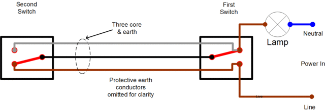
[DIYWiki]
Not really… For starters the switch needs to be a 2-way switch with N/O, NC and COM connections (3 wires). Most wall switches are 1-way (2 wires).
The next problem is there is no way of knowing if the switch is on or off at the moment. Sure, the human can toggle the relay with the app, or the switch with the finger, until the light goes off (or on) but what if you need to know what state things are without being able to see the light? Shelly and Sonoff Mini kind of solves this by moving the switch to its own connection and taking control over the light with the relay. But what if the Sonoff dies? The light won’t work and the electrician is going to need to re-wire the switch.
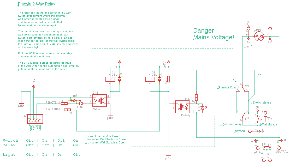
So this is what I came up with so far… put two relays inside the switch box… one to “follow” the 1-way switch and make it into a 2-way - and another to act as the secondary switch in the two-way configuration. As a bonus, there is now a Sense output so the remote controller can know what state the wall switch is in at any given time.
This configuration has a few benefits…
- It is wired just like a normal 2-way switch - and if the controller is completely dead, the switch just works as before and the light can be turned on manually.
- It is passive… there is no “smart” electronics on the board. Just a couple of relays and opto-couplers. It should last for many years without a flash upgrade.
- Low voltage and High voltage are kept separate. The signal cable that controls the relay is separated from the mains side first by an opto-coupler and then by a relay.
Here’s the circuit so far:
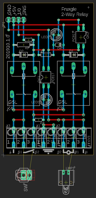
and the board…
I’d love to hear your thoughts… Am I on the right track or chasing a stupid dream?
Rudie
PS. I picked up a mistake on the relay wiring and will correct in the next version.