Hi guys,
I need your help with I small issue with Ether 10 + POE module + Relay Shield carrier. Jon’s relay driver from his episode about Home automation system architecture.
I think I managed to damage my Ether10 board, luckily I have a spare one and can swap them, but cannot understand what potentially could have damaged it.
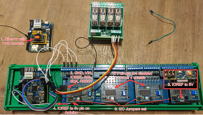
My setup looks like on the photo below.
How it was setup a day ago:
- I have POE module soldered to Ether10. POE module left with the default setting to supply 10V to the carrier.
- Carrier board connected to pins GND, VIN, IOREF, SCL, SDA, RESET on Arduino.
- There is a jumper on one of the relay shields which connects IOREF to 5V
- From one of the relay shields there is a wire from IOREF to 5v pin on Arduino (As carrier board doesn’t have 5V from Arduino). This is to power all relay shields, without this blue power LED on all relay shields is off.
- Pull-ups are disabled on all shields
- I2C Jumpers are set and addressed
With this setup - everything was just working fine, I had a single relay, tested all 32 outputs with it and had no issues.
Recently I received 12VDC relay module (4 relays), it was also working fine but then I discovered that 10V POE from Arduino cannot turn on more than 3 relays, voltage is probably a bit low. I read POE manual and cut a wire on the module to enable 12V, that’s where I got my problem - I cannot connect to my Arduino anymore, it’s not getting an IP and cannot upload any sketches. I do believe something damaged it.
I replaced it with a brand new Ether10, did not connect POE module but just plugged in 12V Power adapter and reconnected all other wires. At the moment everything is working fine, I can drive all relays as 12V is passed to relays now, so it looks good. The only thing is POE module - I would still like to use it, but at this point, I am not sure if everything is connected correctly in terms of power. Basically I have a feeling that I am doing something wrong here or maybe missing something.
In Jon’s short Quad I2C shield carrier test video he is showing this setup without IOREF to 5V jumper (maybe he soldered it on the back side of the shield) and also there is no IOREF to 5V on Arduino wire, but his shields are all powered as blue LED is on.
Can you help to understand if there is something wrong with my setup and how Jon is powering shields in his example? 
