I guess, since pretty much any form of the ESP32 board is technically a prototype board due to the fact that the ESP32 is the SOC, not the actual project board it is attached to, that makes this one I built a hat for a proto board  In my development of the hardware for the package vault, I took an Espressif ESP32 Devkit V1 board and soldered it to a perf board and added some headers and RGB led for testing. I wished that this board came header pin-less. I guess you can get them that way but they are twice the cost. It is an ugly little bug but it does the proto job.
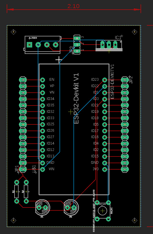
In that vein, now that I have a working model, I thought about making a board that was production that had the same elements but could either have the module soldered on like my test board or I could install header rails and be able to plug/unplug the module from the board. Since I knew I was going to probably always need a push button and a status led of some sorts, I integrated them into the design. And since PCBway is so freaking cheap, I had 10 of them made up. Waiting on them to arrive so I can use one for the vault. Nice thing is, I don’t have to put the headers on the board and can solder wiring directly to it instead if it is going to be a permanent device in a project. Oh yeah, and I integrated a K7805-2000 linear buck converter (12v to 5V, 2A) and a jumper for input and output so I can feed 12v into the board and select whether I feed the ESP with input voltage or a controlled 5v. I also get 5v out on the same screw terminal block that could be an input feed as well or an output from the buck to feed a relay board or what not. Pretty versatile setup.
My ugly bug…
The new design
Next step…
Native board.
Draw up the board with individual parts in place of the module.
(gets a bit addictive after a while…  )
)
Uh, yeah. I can’t see that at the moment. I am ready to throw things. I sent the board design off for manufacture and for some reason, the final file shows that the pads for the LED are actually bonded or connected on BOTH freaking sides of the board, so effectively bridging all the pins together, twice. The component doesn’t show that and as a matter of fact, it shows the opposite. I can’t figure out how to change stuff to get the traces cut between the pads. Fortunately, PCBway caught that in their review, but of course won’t fix it since it’s the ‘cheap’ version of board… no design fixes available. I am trying to sort that out now. I think I will just remove that component and add 2 separate LED’s to replace it. Don’t necessarily need an RGB in there. II can only imagine the headache this would be if I was building this as a native board. There is a LOT of crap on that Espressif board.
Welcome to the wonderful world of board design… 
I’m willing to bet that most of what’s on the Espressif board is completely useless for a finished project. (Particularly the USB support)
My current project started out as a stack of premade modules including an arduino nano & an MCP2515_CAN board in individual parts plus a main unit that includes an Ethernet board. The prototypes were bulky and annoying. The finished (mostly) boards will fit in 2" x 3" x 3/4" boxes.
The real fun begins when I start soldering teeny tiny qfp chips.
Oh, I am sure that this board is actually a nightmare in sharks clothing  It has way more crap on it than I would need for most projects but it has enough stuff to get some relatively basic things done. I am no where near the level of building out my own boards at this point. Hope to get there some day though. This hat just makes using the board a little more… useful. Dropping the pins out the bottom with all the components on one side is stupid unless it is going to be installed in a breadboard during service… and most breadboards won’t accommodate it. Not wide enough. Hence the hat.
I would run Arduino boards for my projects but I can’t stomach paying so much for something like an ethernet or wifi hat for it that costs twice as much as the board. I can’t see using the Arduino boards for any kind of “smart” project because to do so requires some additional hat or what not that costs 2-3 times what the base board does. Hence my attraction to 8266 and 32’s. At least it connects to wifi right out of the box. Would prefer POE ethernet but yet again… cost is prohibitive when a wifi enabled board exists for under $5US (Just bought 10 of them on AliExpress for $45).
Designing a native board for a project seems to me to be a way smarter direction but I am not that smart yet. LOL. For now, I will stick to putting sunglasses on a pig.
1 Like