A niche solution to a niche problem

It’s probably about time I started describing my home automation project, now that it is starting to look like it might just work. The last thing I am debugging is a weird issue with my relay cards, but I am sure I will have that solved soon.

First, a little background.

I have been wanting to set up a home automation project for years. I knew about Clipsal C-BUS, but it felt too expensive and not that extensible. After speaking to a friend that has an interest in this space, he convinced me that the best way to go was a commercial product called Loxone. It was quite good, heaps cheaper than C-BUS and had really good software to program the thing. Unfortunately, after running for 2 years, the ethernet bus stopped working on the central Loxone Miniserver and I was faced with spending quite a bit of money to purchase the most expensive part of the system. At that point I became aware of Superhouse (thanks @jon) and decided that the best way forward was to ditch the commercial solution in favour of a more open source approach.

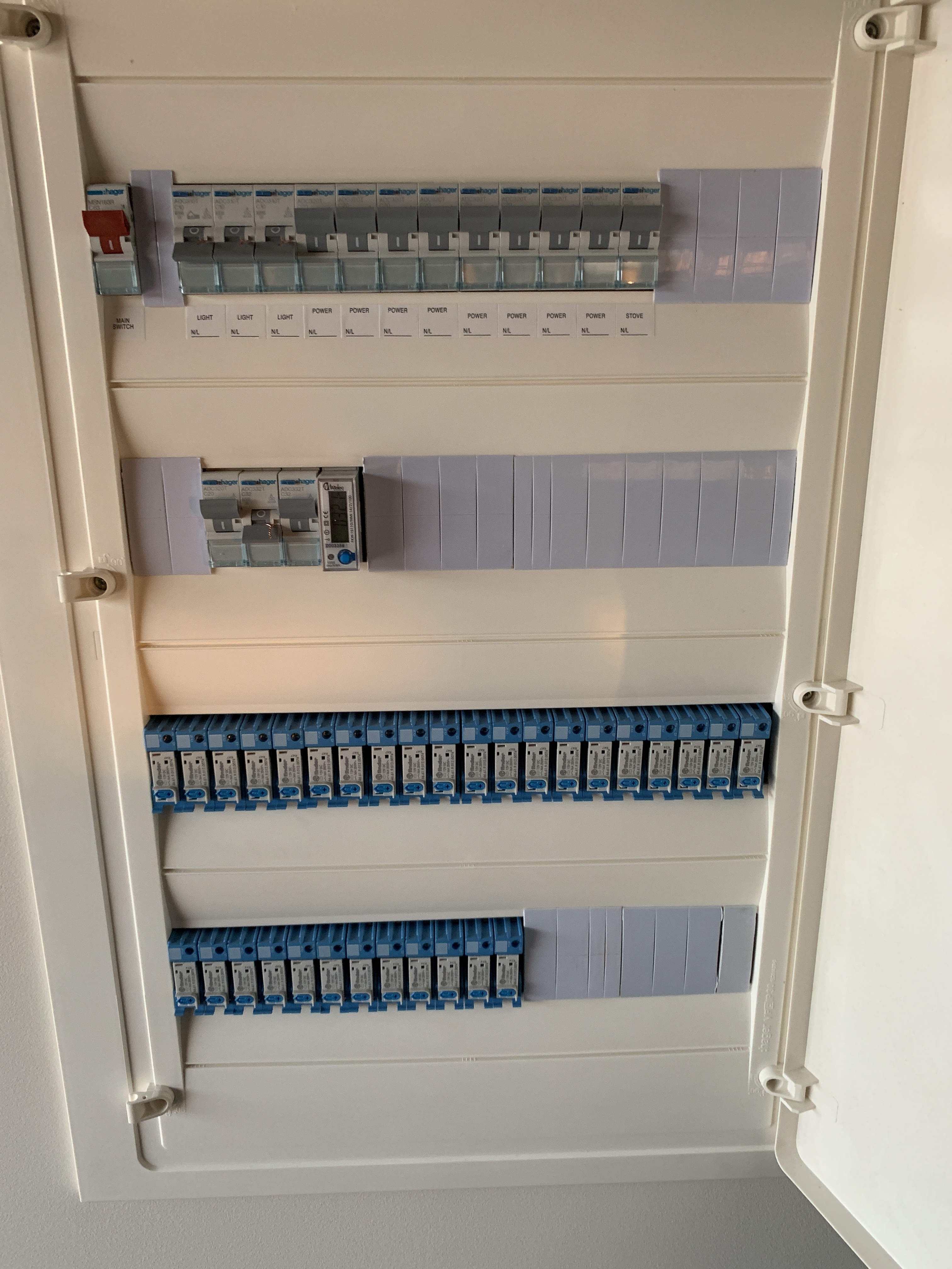
I wanted to start with something simple that would be limited to controlling lights. One of my absolute requirements was that light switches and relays must be hard-wired for all the core lights to reduce the kinds of things that would cause a failure.

I started with a light switch controller shown on one of the Superhouse videos, and that worked really well. The only problem was that I was having trouble finding a solution for the actual light switch that you touch that would also be acceptable to my darling wife. It was at that point that a conversation with a friend in the UK led us to start an ambitious project to tick all my boxes.

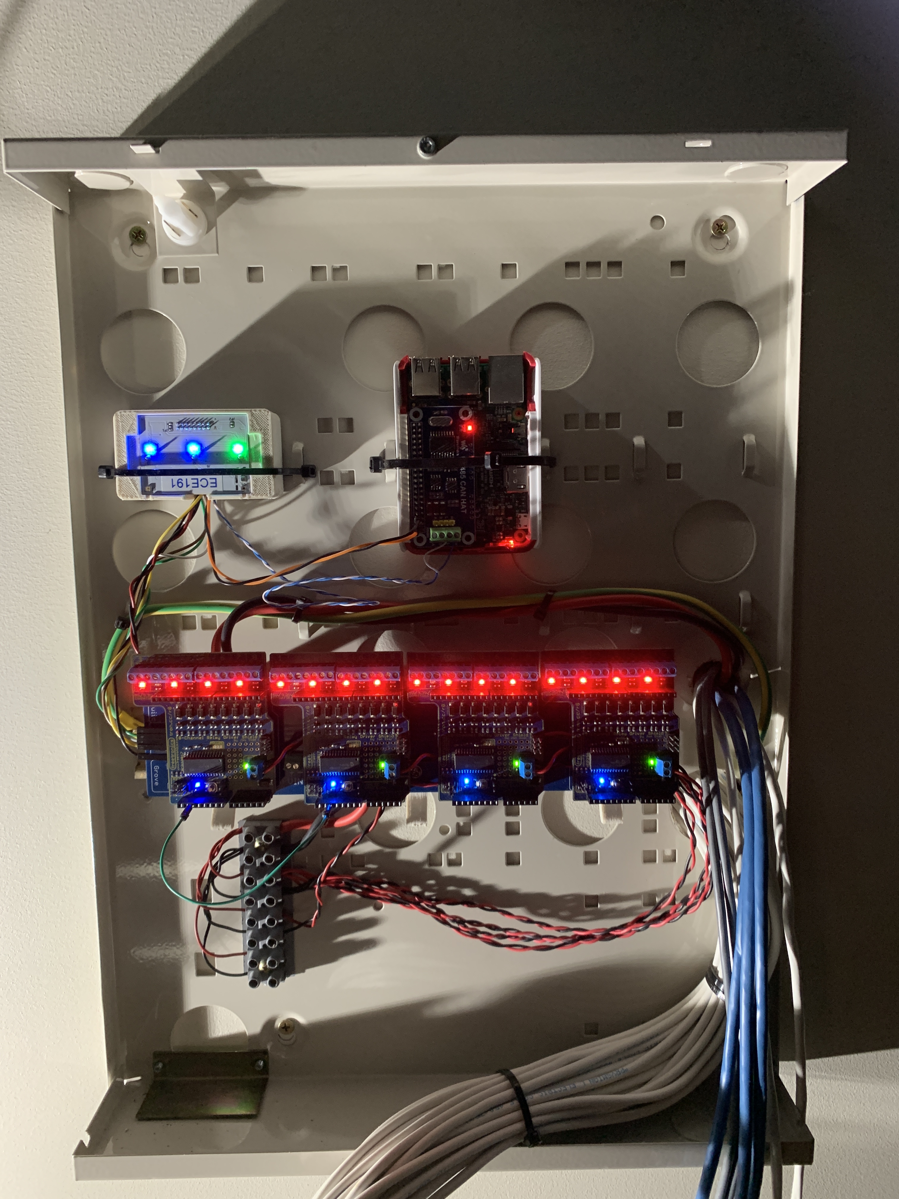
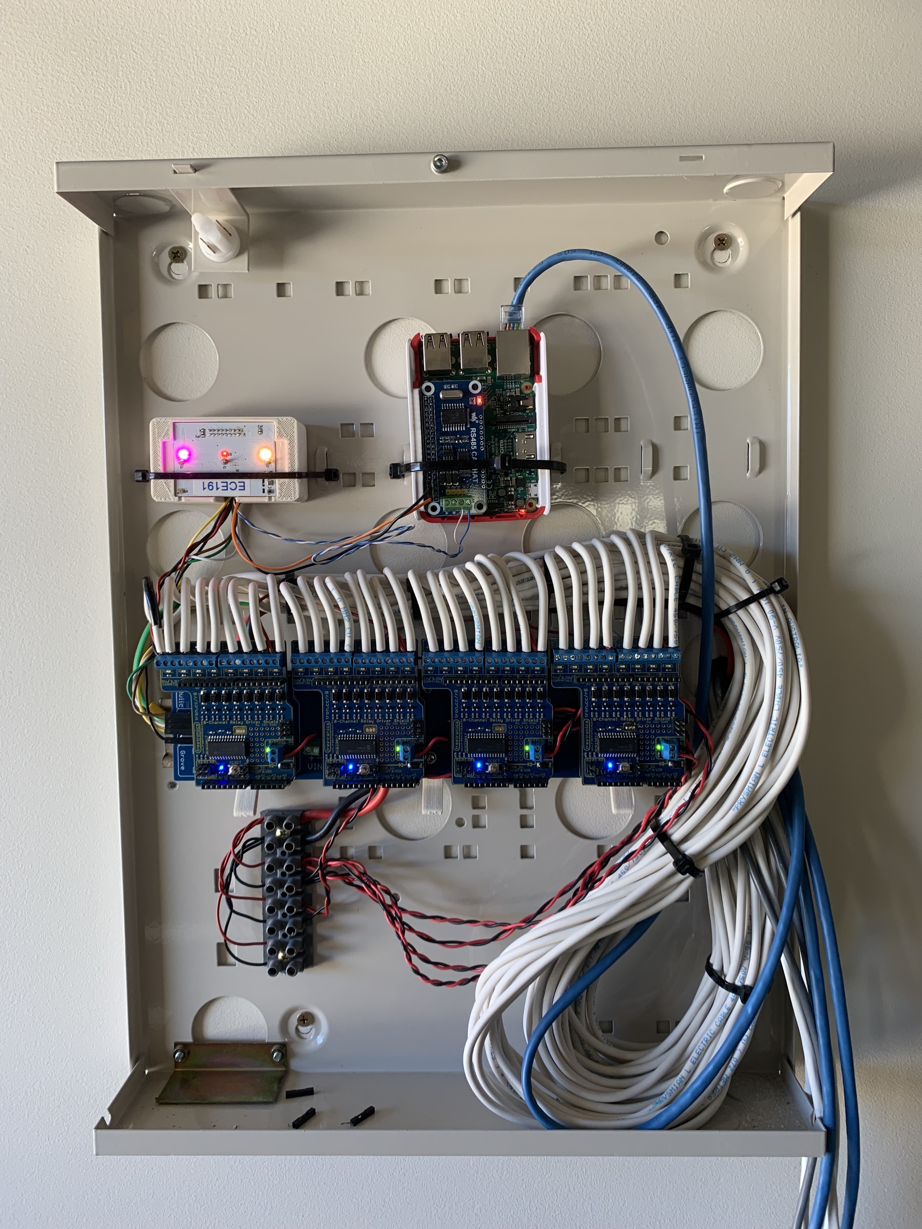
The idea was simple. Use an off-the-shelf glass capacitive touch light switch from Livolo, and replace the brains with an microcontroller that would communicate via a wired network, and fire relays in the switchboard using a bunch of Superhouse Relay8 boards. It has taken us about 8 months to get to this point, but the results are looking really good.

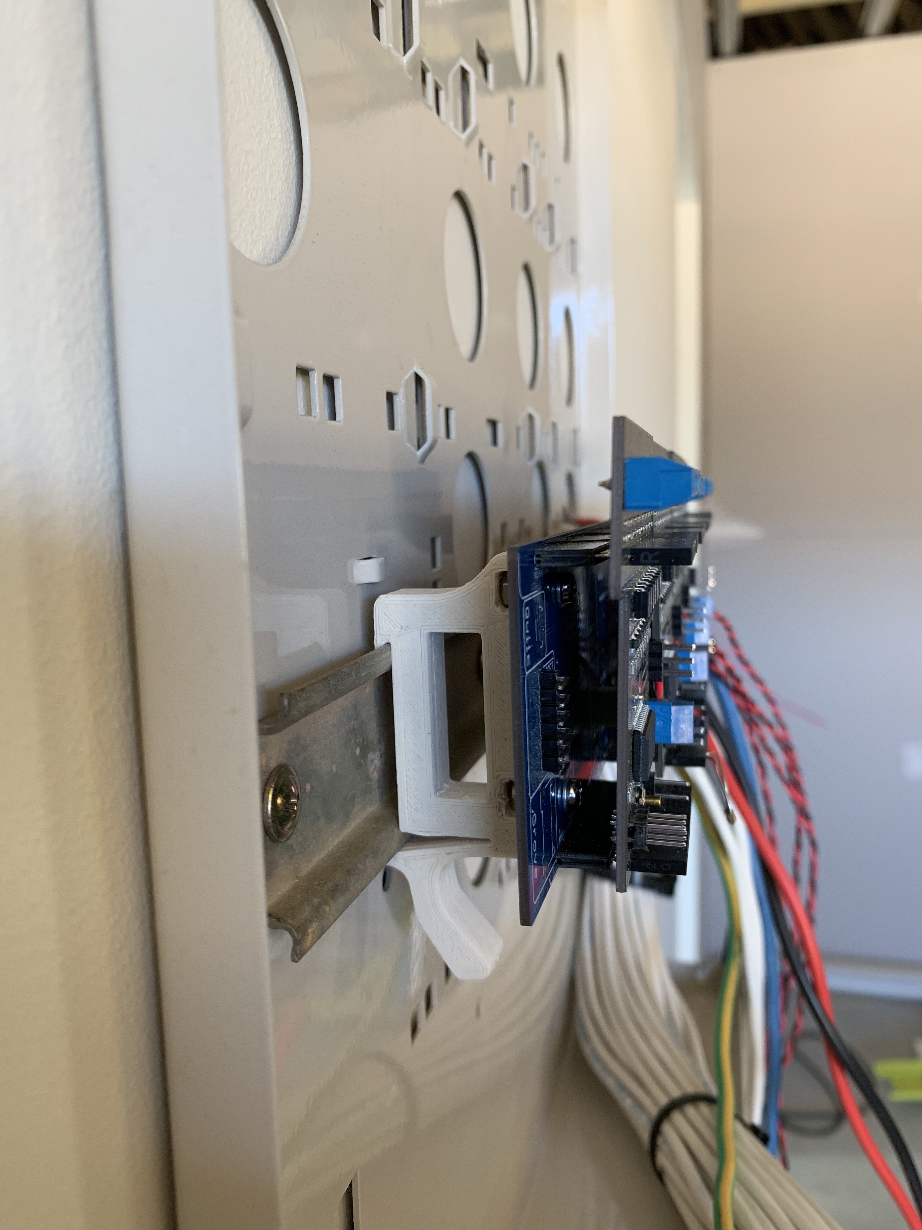
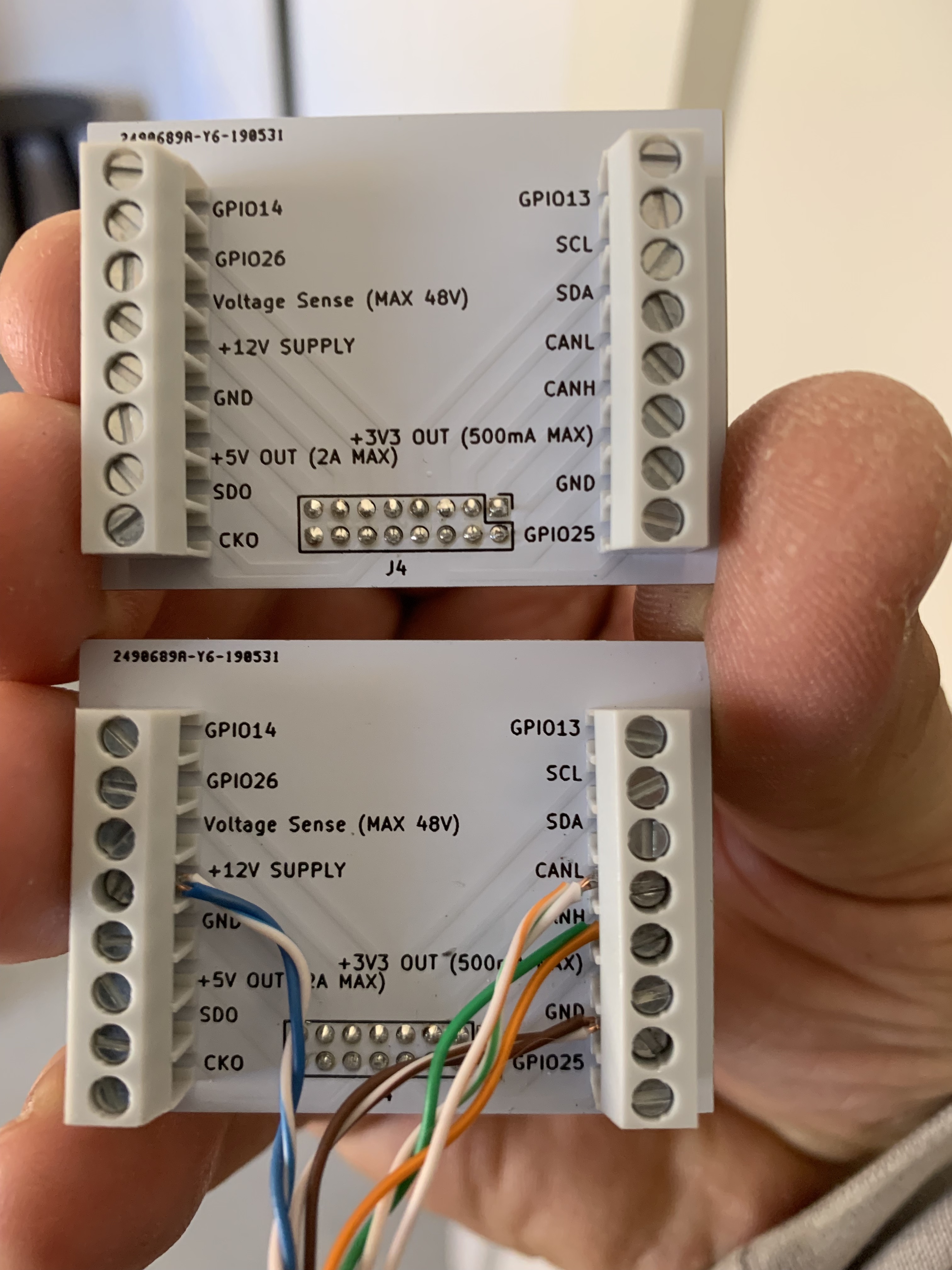
For those playing at home, each lightswitch has a ESP32 microcontroller, a bunch of sensors (temperature, humidity, ambient light) connected to an I2C bus, and they communicate to all other lightswitches on a CAN bus. We have assumed a supply voltage of 12v, and have built in voltage regulators for 5v and 3.3v. We have exposed the 4 spare GPIO pins, as well as the I2C bus and voltage rails to a header that interfaces to the building cabling via a daughter board. We have only made one version, which has 3 light switches, and each switch has an RGB LED that relates to that switch. Currently, I am using Node Red to bring it all together.

I’m sorry I don’t have any pictures just yet, but everything is still a mess of cables on my bench, and I will add some pictures as I get things permanently installed. If this project is of interest to anyone, I am happy to answer any questions, and would welcome comments.

Thanks.

1 Like

That sounds awesome. What chip did you use for CAN? Why CAN and not RS485 for interest sake?

Rudie

Hi Rudie,

I did originally consider using RS485 but we went down the path of CAN because the ESP32 has a CAN 2.0 bus, so it was simple to implement. I am also currently performing an electric vehicle conversion which the CAN bus would be useful for, so it kind of moved me in that direction.

1 Like

I’m in the middle of doing some wheelchair projects using CAN, and I’ve found the complexity of implementing protocols like CANopen has been quite daunting. I have the book “Embedded Networking with CAN and CANopen” sitting right here on my desk but so far we’ve been just sending very simple messages with things like joystick position, and using a different CAN frame ID for each parameter that we want to send.

That won’t scale very well so I want to use something like CANopen instead.

How are you handling the protocol side of things? I think CAN is a great option for home automation and it’d be nice to have some conventions around how to implement it, so that we can make things that work together.

That sounds like a great idea @jon. My project is actually a collaboration between myself and a friend in the UK. All the hardware and software for our project will be released open source just as soon as I have it working nicely for my “simple” system. Hopefully this won’t be too far away as the lighting control is quickly becoming the last thing before we can have council sign-off for our house.

It’s about time I give an update. I have used 4 x Superhouse Relay8 boards, mounted on a nifty carrier board that @jon put together for me. The mounts are 3d printed in ABS from a design by @Bedrock.

I am located in Australia so I designed this cabinet to be exclusively ELV so I can happily play without needing my electrician to help out. The wires I have included are:

  • 1 x 2.5mm Green/Yellow - Electrical earth as the ELV cabinet is metal
  • 33 x 1mm White (Double Insulated) - 32 Relay coil triggers and a common going to the main electrical switchboard
  • 6mm Red and Black - 12VDC from regulated power supply
  • 3 x Cat5 UTP - Ethernet and some spares
  • 2 x Belden 8723 - 2 pair shielded and screened for CAN and a spare
  • 3 x 4 core 14/0.20 Security Cable - Just because

One of the last things I needed to do before moving the system from my bench to actually start installing it was to successfully test the relays. They would work for ages and then spontaneously stop working. This ended up being my own stupid fault as for some reason I stopped connecting the reset pin sometime between my original Arduino prototype to my ESP32 CANswitch.

Pro tip: The reset pin on these units is connected to the reset pin on the MCP23017 and according to the datasheet must be tied to vref (in my case 3.3v) via a resistor. Not connecting it like this results in a floating reference where weird stuff happens and you lose your sanity.

2 Likes

Is the metal housing a security equipment box …???

Hi @FrankMc.

You’ve got a keen eye. It is from a Tecom Challenger that I had kicking around from a former life.

1 Like

This is looking great!

1 Like

Quick update. I have successfully replicated what was working on the bench to be in place in the cabinet. Running a burn-in test.

The unit on the left is a CANswitch which has 12VDC input and is regulating 5V to power the Raspberry Pi, and 3.3V to power the Relay8’s. The Raspberry Pi has a CAN hat which I use to communicate with the CANswitch using… CAN. The CAN network is currently limited to these two devices, but I will be including more CANswitches soon that are the actual light switches that will be mounted to the wall.

My LV switchboard has 32 relays that are pre-wired to the double-insulated cables hanging out of the ELV cabinet. I will be connecting these hopefully tonight.

3 Likes

Looking good …Is the rpi the master on the can bus ??? …can you have multi masters on canbus ??..Finder relays ???

CAN is a multi-master bus, this way you don’t have a single master that could take the whole system down. You do cable it in a daisy chain fashion though, so from a wiring point of view it you need to take that into account.

Yep, finder relays. They are the most space efficient ones I have come across, and available in a wide range of coil voltages. I am using 46.61.9.012.0074 which are 12VDC.

2 Likes

Very very nice.

Can you elaborate on how to “play without getting the electrician out”? I assume the trick is to have the high voltage relays in the DB board and the low voltage control gear remote? Does it count to have the HV relay inside the light switch but toggle it with LV from a distance? Will that pass?

Rudie

Hi @Rudshep,

Spot on. By splitting the LV and ELV into two seperate cabinets, I am able to legally reconfigure anything I want in the ELV cabinet, leaving the LV cabinet to the licensed electrician. I have also earthed the ELV cabinet, and used double-insulated cables to pass between the cabinets, all designed to reduce the risk of bad things happening.

The relays that actually switch the 240VAC are all located in the LV cabinet, and there is absolutely no LV in the ELV cabinet.

I have also now wired up the relays and confirmed that they are working. I only have one CANswitch hooked up at the moment, so I have used the three buttons on the CANswitch to allow the electrician to test the entire system. The left button and right buttons are used to move which relay you want to control, and the middle button sets/unsets the relay. I even have the RGB LEDs change based on the relay index position.

[ Previous ] [ Set / Unset ] [ Next ]

It’s starting to come together.

2 Likes

Brilliant!

I’m definitely going to use the “sparky test interface” in my build now. Someone with absolutely no idea how the thing hangs together should still be able to test the basics - even operate the system in “manual” mode. Plan B if the Pi die.

Rudie

1 Like

I’m now running out the final terminations to all the lightswitches. When I started this project, I decided to go with a star configuration, but as CAN is a bus, I need to flatten it out. It means that the CAN bus is logically a daisy chain from device to device, but I have kept the power supply a logical star to reduce cable length. I have decided to use the passive PoE convention of Blue/Blue-White being positive supply, and Brown/Brown-White being negative supply.

1 Like

Looking good!

I discovered last night that the IEEE is releasing the 802.3cg standard. This is a Single pair, Multi-drop bus based on Ethernet! So basically the simplicity and robustness of RS485, CAN - that you can run standard IP frames over. I am keen to see what this brings.

The good news for us wire-lovers is the wiring is compatible with our “legacy” buses already in our walls so the good old Orange Pair is here to stay. Follow PoE convention for power and there will be minimal rewiring necessary when the new goodies arrive one day.

I am curious about what I noticed on your photo… I see the orange (Rx on Eth) is wired in parallel to green (Tx on Eth) on the CANL and CANH pins. On RS485 only orange A/B is used and they go A on A and B on B in the chain and the green pair is redundant (and wasted I suppose). Some people use Green for a reverse channel for full duplex. Is CAN different or are you doing some clever sorcery here?

Rudie

Hi @Rudshep,

I had to flatten out the physical star topology to a logical daisy-chain as all the specs I have read say that CAN must be on a flat bus (happy to be proven wrong here). I have used the solid green and orange cables as CAN HIGH with their mates as CAN LOW. I simply go in on one colour and out on the other, and loop to the next device at the patch panel. Have a closer look at the wiring loom at the patch panel and it will all make sense.

The Raspberry Pi CAN hat has a termination resistor, so I put that at the start of the bus, with a 120 ohm termination resistor at the extreme other end. Seems to work well.

1 Like

Clever move to flatten the bus like that. All the CAN design docs I’ve read talk about minimising the stub-length when designing devices, so the CAN transceiver is closely attached to the pass-through between the 2 connectors and not turning it into a “Y” shape.

This explanation on page 9 of TI guide to CAN physical layer requirements is very interesting:

Since stub-lines are unterminated, signal reflections can develop in a stub that drive signal levels back and forth across a receiver’s input thresholds, creating errors. Bit-sampling occurs near the end of a bit, so it is mandatory that all signal reflections in a CAN stub-line be attenuated before or during the propagation delay segment in Figure 15 to provide an adequate margin of safety.

To minimized reflections, stub-line length should not exceed one-third (1/3) of the line’s critical length. Beyond this stub-length, many variables come into play since the stub is no longer considered to be a lumped parameter. This is the maximum length that a stub remains invisible to a transmission line.

The critical length of a bus line occurs at the point where the down-and-back propagation delay (tprop(total)) of a signal through a line equals the transition time (t) of a signal (the greater of the rise or fall times).

Network Critical Length = t= tprop(total)

Therefore, a typical CAN driver may have a 50 ns transition time, and when considering a typical twisted-pair transmission line prop delay of 5 ns/m, the down-and-back delay for one meter becomes 10ns/m. The critical length becomes 5 m (50 ns / 10ns/m = 5 m), and the max un-terminated stub length for the network is 1/3rd of the critical length, or 5/3 m (1.67 m).

This is from: http://www.ti.com/lit/an/slla270/slla270.pdf

1 Like

Nice work on this! I had started a project a while back for smart light switches but haven’t gotten back to it yet.

1 Like