Hi Guys
Been following this thread with interest…A lot of it im not familiar with as i program my pic chips in ASM and have dabbled a bit in picbasic …Im guessing its “C” programming ???..I understand programming using states as i have seen it done in PLC stuff…Chris,s, code i found easier to follow…Some questions …what is millis()…??..timer = 0…im assuming your preloading a variablefor a timer with with 0…???..if so im curious why you would clear your timers…is it because its a common timer for all timed functions and your then preload with the declared variable s…Thanks Frank
Hey Frank! The programming language is C++ or CPP. I am not all that seasoned with it either but since Chris dug me out of the weeds, I have time to explain what I DO know…lol. millis() is a timer. Short for Milliseconds. It is a “non-blocking” timer meaning it doesn’t lock up the processor when it is working like the other option in CPP… the delay(), which makes it impossible to do anything but count when it is called. When the program is powered on, it starts a counter from zero. That counter rolls along until it loops back to zero somewhere in the 47.5 day range (the exact number eludes me at the moment). So… you call a count against millis() with an integer and do some simple math…( millis() - a_timer) and you get a number to use for elapsed time. The entire problem I was having is that I either wasn’t invoking a timer properly or wasn’t clearing it so the number the simple equation came back with was already higher than my interval used to count against. I had created a timer for EACH use… led blink, relay unlock, relay lock, etc, and then wasn’t invoking or clearing them properly. No idea that I could use one timer for all and just clear it before each use. So basically what is going on is to take millis()… the current time on the clock now, and subtract against accumulated time on a variable then check it against your set value. If the variable time is still less than your required timer, you let the processor do what it needs to do and check back in on the next loop through. If it is greater than or equal to your timer value then you rewrite the variable to match the current millis() which essentially zero’s the counter because the two numbers are now the same, netting zero when they are subtracted. In the case of Chris’s code, you are simply resetting the variable to zero after the counter has met your timer value so it can be invoked again the next time it is needed. The timer value dictates what number it needs to get to to become TRUE each time through.
So how was that for overexplained? The concept I got, the delivery… not so much 
1 Like
Hi Grant
Thanks for the clarification…If i understand correctly you can use the same timer as only 1 timer is used in each STATE… It appears to me the timers are counting up ?? …im use to counting down  …With my asm code i use interrupts for timing …I preload the timer(s) and set an enable bit…it gets check in the interrupt service routine ,if enabled decrements the timer value ,checks for zero and if zero sets a done bit which and clears the enable bit…Sounds like the milli() is a free running timer so when starting a timer you add your timer delay value to the current milli() value and then compare that value to milli() every loop …???.. i think i also have trouble explaining things ;-)…Cheers Frank
Essentially you are correct. There is ways to do interrupt timers in CPP programming as well… and I assume they are driven with the millis() setup but I could totally be wrong on that. The key with millis() is that it starts when the program starts and runs continuously, just like a stopwatch that never stops counting. You can’t get zero back so you just take the current time and start your counnt from there. When you set up a timer, you refer to what time is on the millis() clock and that is the base for your math. You initialze your variable against millis(), by synchronizing it with millis() (creating a hard zero… that took me a bit to understand… sorry @moinmoin  ). That number stays static and the processor then keeps subtracting millis() from the variable set point and you get an increasingly larger number. When you get to your timer interval, if you don’t code like me, then you reinitialize the variable with the current millis() time and you have effectively reset your counter. HOWEVER… millis() keeps incrementing so each and every time you want to count something, you have to keep reinitializing your variable to sync it with the current time.
2 Likes
From what I understand:
millis() is the Arduino clock, not a timer, and is interrupt driven, so it won’t tick within an interrupt handler, or any critical section where interrupts are disabled.
You can make a timer out of a clock basically in one of two ways:
-
Take the time when you start your timer, and check whether the difference between that and the current clock time exceeds the required amount. This is what is being done there.
-
Add your delay to the current clock time, and wait until the clock catches up. This method has the downside that it doesn’t handle wrapping very well, and we know the millis() clock wraps.
So basically, either way, you start your timer by copying the clock time into your timer variable, and then you check against it periodically to see if it’s finished. It just so happens that calculating the difference and checking against the timer duration, is more robust against clock wrapping, as long as the math is done with the same number type as the clock — unsigned long.
This also has an advantage against count-down timers; for count-down timers, you have to decrement all the concurrent timers every tick, firing off the handlers of the ones that expire. Using a clock, you have exactly one time reference to keep ticking, and just need to check all your concurrent timers against it as you want.
That’s a really nice job! It just needs a loudspeaker now so you can shout at suspicious looking folk.
1 Like
I spent a bunch of time over the last few days doing the tweaks to the code that @chris graciously corrected for me and I have a working beta now to go upload into my vault. That should remove all outside influence on the thing and negate the need for an active MQTT connection to keep it working. It still has MQTT elements but is mostly just status type stuff. i will get the current code up on my Github page in the next day or two so anybody interested can look at that.
Being as this has kind of taken on a life of it’s own, I received a suggestion to take this into it’s own world as a full blown open source project kind of thing. It is already but I don’t know that I want to mire Jon’s forum down with what might or might not go on with it in the future. So, with that, i am working on creating “The Package Vault Project”. I am not a web developer and really don’t know what the hell I am doing with that but it will probably end up being yet another thing i add to my plate of stuff to work on. Seems like another money pit to burn cash in and I am good at that, so why not?  But I will try and keep whatever comes of that out of here. If anyone has thoughts on this and want to pass it along, please PM me with it so as to not create any conflict with forum policies.
On a tangentially connected theme here, I am looking for input on what kinds of things you could see integrated into my vault. Right now, it is just basically an IoT device but mostly just the “T” part. It is relatively self contained and could easily be totally self contained but I am looking at coming up with a list of what kind of options people can come up with for control, function and access. I just sprung for a Weigand compatible HID reader, some cards and a separate Weigand compatible keypad that reads HID and RFID fobs to play around with for direct access. Currently, it requires MQTT for resetting and unlocking the box. I toyed with a keyswitch but that is just too 1950’s. This is a smart vault dang it! Security! This could get expensive as hell in a hurry but I gotta try out all the possibilities!
So ideas I have tossed around:
-Access card or FOB
-NFC phone control
-Keypad
-Some sort of phone app that uses IFTTT
-Obviously MQTT connectivity, and/or control through Alexa and Google Home, which I have neither of because my internet sucks balls
All of these ideas have Arduino/ESP32 projects in the wild that I could customize so they wouldn’t be horribly hard to add on. What other kinds of stuff could you see integrated into something like this? I have the camera onboard and that has kind of turned into an annoyance simply due to lack of products that exist that fit the bill currently. I mean, it works. The field of view is just so small because you can only fisheye a picture so much and it is unusable. No camera gets a good field of view in 2 feet.
1 Like
Hi Grant ,Right now as I type this I have been thinking about your vault box. One feature I would like is having a button external as a request to open. For instance when you get a second parcel drop your not at home they press the open request button you get notified and can confirm it’s valid parcel drop via camera , you remotely reset the system and it relocks after they close the lid …
Blockquote
Im seriuosly thinking of using this little gangbox that i have to make a vault …if i do i will use a pic based board to control it but would like some wireless stuff connected to it…I have read someone has modded an esp8266 as a broker to work with Homevision @ 19600 baud so im hoping i can venture down that path…My main issue with this gangbox is how to mechanically mod it so if the locked fails i can still get into it…Cheers Frank
1 Like
YES! I do like the delivery request option idea. Something to chew on for sure. It looks like the stock locking option on your box is a padlock clamped on the lock tab that drops through a hole in that pocket in the front of the box? Drop a couple more pictures of it on here and I am sure I can come up with ideas since I have already been down this road with mine. I have a thought but need to see better how it currently locks to be sure.
1 Like
Absolutely! I am drawing it up now…
1 Like
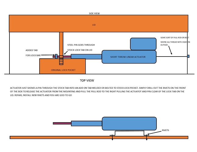
I have an idea. Picture is below. It is a super simple design. Take a short throw linear actuator and put a metal rod on it. Mount that actuator into the cabinet on a bracket that is held to the inside front of the box with pop rivets. Put a small pull rod, or bolt or all thread on the back of the actuator so you can pull on it if needed. The actuator does not move, only it’s rod. When activated, it extends, shoving the rod through the stock locking tab on the lid into another added tab welded or bolted to the top side of the lock pocket. The lid can’t be lifted. Should something fail, just drill out the pop rivets, freeing up the entire actuator assembly. Grab the end of the pull rod and pull the entire actuator assembly clear of the lock tab and open the lid. Repair, wash, rinse, repeat! No additional mechanical parts to fail
1 Like
Looks good , Im thinking if you make the added tab extends thru the lock pocket for the lock and and the tab has a flat plate welded so when the linear actuator retracts it doesnt let the plate and lock drop out…Also have the actuator mounted on a plate fixed to the lid instead then it lifts ??
Thanks Frank…hope that makes sense …
All good options. My thinking is that the wiring for the functional parts of the box should be as out of sight as possible so someone doesn’t go in and cut them then come back later and take whatever was delivered. With the actuator in the lid, you have flexible wiring at the hinge point that could be compromised.
There is quite a few ideas that i thought of that would all work. The bottom line is making sure that you can get the box opened if the lock system fails to unlock. That part needs to be as damage-free so that if you do have to do it, it can be easily corrected to put the box back into service. Making the most of the stock locking mechanisms as much as possible, whatever they may be, is also easier.
1 Like
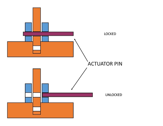
I reread your post and I think I may have confused you possibly? The added tab(S) in my drawing is actually welded in. I noticed I failed to include the second tab. It’s purpose it to have something for the actuator pin to push through when it is locked. The pin in its retracted position is completely clear of the stock lock tab that is protruding down through the top of the lock pocket. When it actuates, it pushes the pin through the stock lock tab and into a hole in the added tab on the opposite side. There is no physical lock of any kind on the box, such as a padlock. From the outside, it would just look like someone forgot to put on a padlock to secure it. But that is all done inside. The purpose for the added tab is that if you relied only on the actuator pin through the stock lock tab, they could provide enough leverage to bend the actuator pin up and break its mount. That pin actually pushes through both of the tabs and essentially sandwiches the stock lock tab. Both of those tabs are the reason why the actuator would have to have some sort of built in pull rod on it. Just removing the rivets to free the bracket would not release the lock pin. You would then have to pull the entire actuator and pin back out of the tabs to clear the pin. The only time the pull bar would even be able to be pulled on is if the rivets had been drilled out and pushed through to the inside of the cabinet. Overall it is a super simple design but a little bit more complicated to get open than just picking a lock. I included a better picture of what i am talking about…
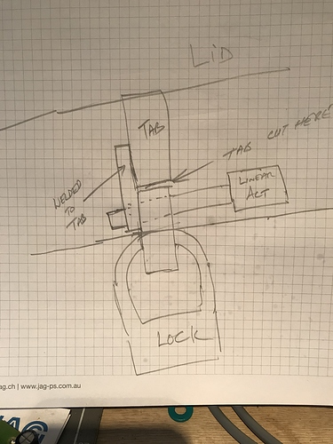
Im thinking of cutting the current locking tab and welding your lhs tab to the top section of the tab …Still have the lock mounted of the lid and the lock still connected …remove the rh tab in your pic…and it should work i hope…i just tried to order a couple of linear actuators from your source but shipping was $90 US so i,ll try and source locally…
Look at Ali Express. Same products basically but cheaper shipping
MannHwa Smart Home Electrical
Only difference between what I got and these is the color of anodizing a far as I can tell… and FAR cheaper
1 Like
The new working code as it stands has been updated on my Git Repository Page I have some work yet to do… but does that ever end? Me thinks not…

 …With my asm code i use interrupts for timing …I preload the timer(s) and set an enable bit…it gets check in the interrupt service routine ,if enabled decrements the timer value ,checks for zero and if zero sets a done bit which and clears the enable bit…Sounds like the milli() is a free running timer so when starting a timer you add your timer delay value to the current milli() value and then compare that value to milli() every loop …???.. i think i also have trouble explaining things ;-)…Cheers Frank
 ). That number stays static and the processor then keeps subtracting millis() from the variable set point and you get an increasingly larger number. When you get to your timer interval, if you don’t code like me, then you reinitialize the variable with the current millis() time and you have effectively reset your counter. HOWEVER… millis() keeps incrementing so each and every time you want to count something, you have to keep reinitializing your variable to sync it with the current time.
 But I will try and keep whatever comes of that out of here. If anyone has thoughts on this and want to pass it along, please PM me with it so as to not create any conflict with forum policies.


