Absolutely! I am drawing it up now…
1 Like
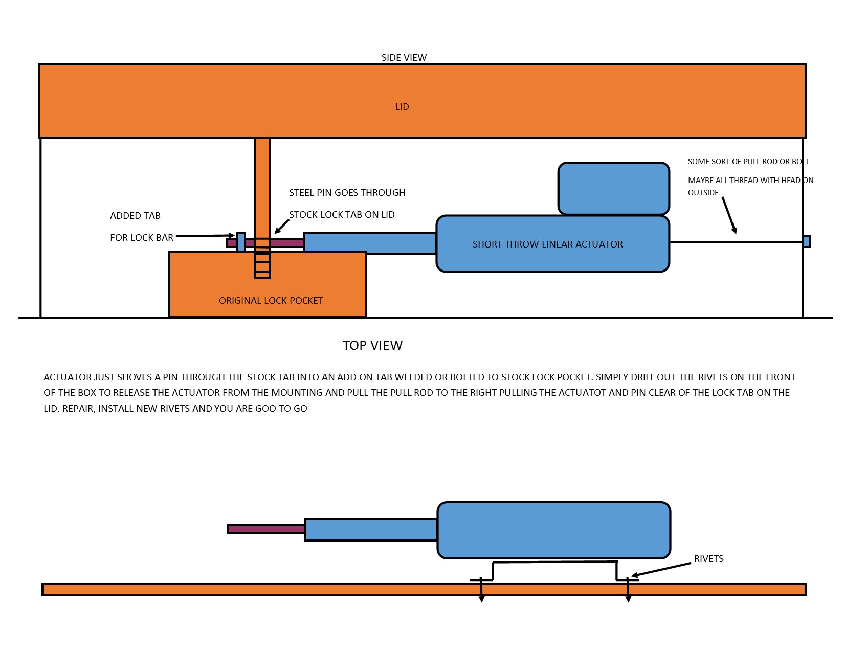
I have an idea. Picture is below. It is a super simple design. Take a short throw linear actuator and put a metal rod on it. Mount that actuator into the cabinet on a bracket that is held to the inside front of the box with pop rivets. Put a small pull rod, or bolt or all thread on the back of the actuator so you can pull on it if needed. The actuator does not move, only it’s rod. When activated, it extends, shoving the rod through the stock locking tab on the lid into another added tab welded or bolted to the top side of the lock pocket. The lid can’t be lifted. Should something fail, just drill out the pop rivets, freeing up the entire actuator assembly. Grab the end of the pull rod and pull the entire actuator assembly clear of the lock tab and open the lid. Repair, wash, rinse, repeat! No additional mechanical parts to fail
1 Like
Looks good , Im thinking if you make the added tab extends thru the lock pocket for the lock and and the tab has a flat plate welded so when the linear actuator retracts it doesnt let the plate and lock drop out…Also have the actuator mounted on a plate fixed to the lid instead then it lifts ??
Thanks Frank…hope that makes sense …
All good options. My thinking is that the wiring for the functional parts of the box should be as out of sight as possible so someone doesn’t go in and cut them then come back later and take whatever was delivered. With the actuator in the lid, you have flexible wiring at the hinge point that could be compromised.
There is quite a few ideas that i thought of that would all work. The bottom line is making sure that you can get the box opened if the lock system fails to unlock. That part needs to be as damage-free so that if you do have to do it, it can be easily corrected to put the box back into service. Making the most of the stock locking mechanisms as much as possible, whatever they may be, is also easier.
1 Like
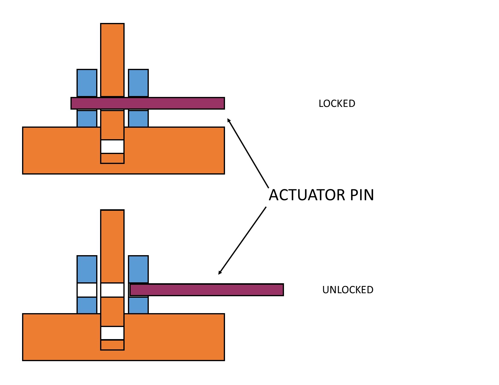
I reread your post and I think I may have confused you possibly? The added tab(S) in my drawing is actually welded in. I noticed I failed to include the second tab. It’s purpose it to have something for the actuator pin to push through when it is locked. The pin in its retracted position is completely clear of the stock lock tab that is protruding down through the top of the lock pocket. When it actuates, it pushes the pin through the stock lock tab and into a hole in the added tab on the opposite side. There is no physical lock of any kind on the box, such as a padlock. From the outside, it would just look like someone forgot to put on a padlock to secure it. But that is all done inside. The purpose for the added tab is that if you relied only on the actuator pin through the stock lock tab, they could provide enough leverage to bend the actuator pin up and break its mount. That pin actually pushes through both of the tabs and essentially sandwiches the stock lock tab. Both of those tabs are the reason why the actuator would have to have some sort of built in pull rod on it. Just removing the rivets to free the bracket would not release the lock pin. You would then have to pull the entire actuator and pin back out of the tabs to clear the pin. The only time the pull bar would even be able to be pulled on is if the rivets had been drilled out and pushed through to the inside of the cabinet. Overall it is a super simple design but a little bit more complicated to get open than just picking a lock. I included a better picture of what i am talking about…
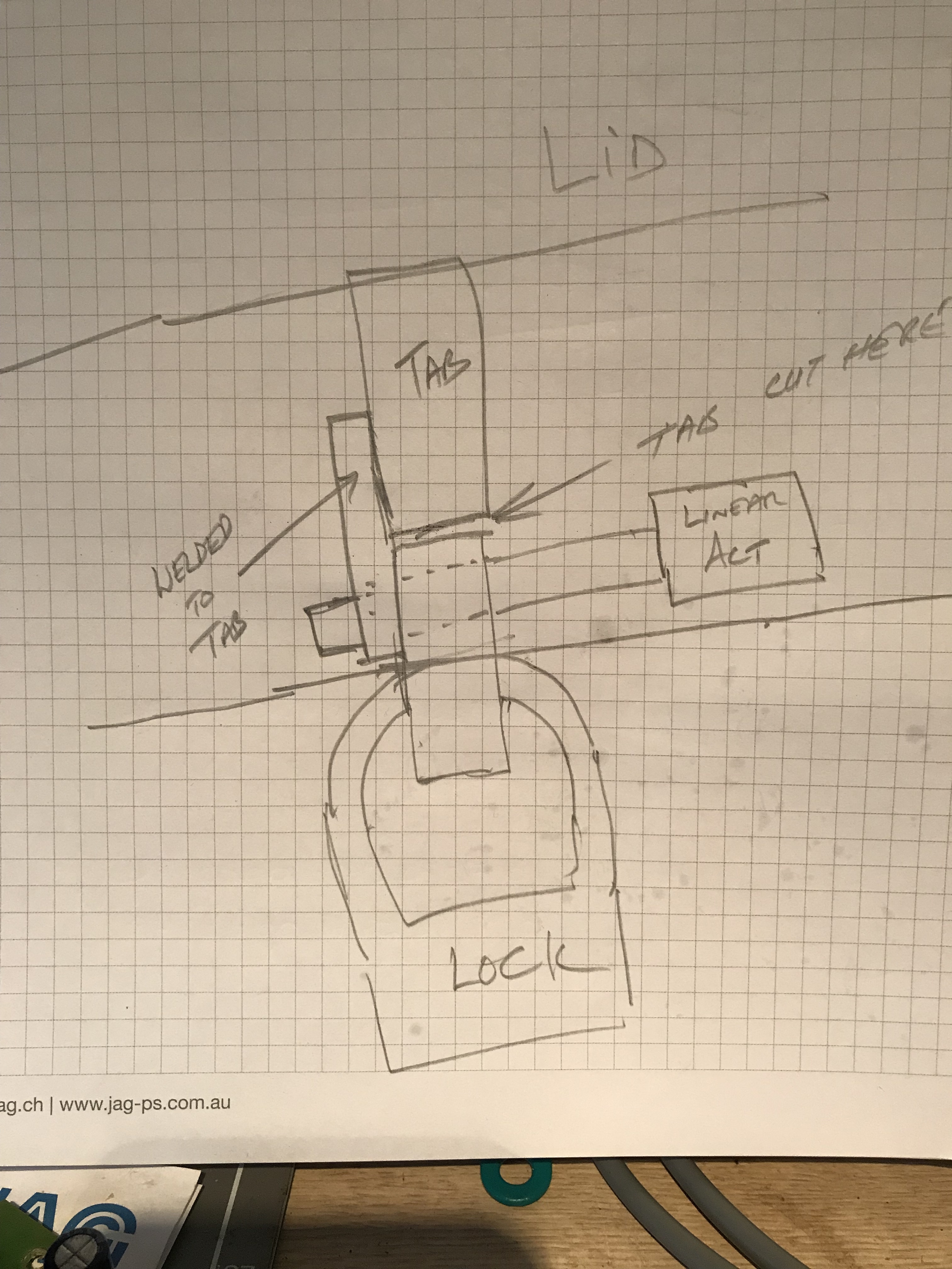
Im thinking of cutting the current locking tab and welding your lhs tab to the top section of the tab …Still have the lock mounted of the lid and the lock still connected …remove the rh tab in your pic…and it should work i hope…i just tried to order a couple of linear actuators from your source but shipping was $90 US so i,ll try and source locally…
Look at Ali Express. Same products basically but cheaper shipping
Only difference between what I got and these is the color of anodizing a far as I can tell… and FAR cheaper
1 Like
The new working code as it stands has been updated on my Git Repository Page I have some work yet to do… but does that ever end? Me thinks not…
Hi Grant
Been thinking about the Panic button in case someone did lock themselves inside and coming from an industrial electrical background i dont think i would be happy totally relying on the electronics to function to unlock the lid in this situation…Have attached a pic of how i think might bea better solution…

I had that thought too which is why I rejiggered the panic switch idea and used a 12v latching push button with a backlight. I have yet to complete that integration as I am going to be building that into my custom designed control board. I don’t have a schematic drawn up but it’s basically like this…
The actuator is 12v at about 1A when it is running. The switch is rated at much higher than that, though it won’t be passing any kind of amperage, and it will get a direct 12v feed. I plan to install a set of 25A automotive relays that the outputs from the regular relays for the actuator passes through on the normally closed side (I actually have a package that I can’t recall off the top of my head that is for 240v, 30A that is around $4per that I planned to use, and it is through hole). As long as the button is released, the “panic” relays are idle and allow the microcontrollers relay outputs to pass through and all works normal. If the button is pushed (and subsequently latched) it will power those panic relays and close them to the NO side and one side will have +12v and the other GND. That will totally bypass any output from the other relays and force the actuator to unlock. Because it has an internal limit switch, it will go full stroke and just shut off. As long as the panic button is latched, it will continue to bypass the other relay outputs until the battery goes dead, at which time, the microcontroller won’t be able to do anything anyway. Resetting that panic mode actuation will be as easy as pressing the button again to unlatch the switch, releasing the panic relays and allowing for full electrical control from the regular control relays.
The panic function is two fold anyway. The primary element is a PIR sensor mounted in the lid of the controller box. It is coded so that once the box is locked down, it is regularly polled and if it is activated by either heat signature or movement, it will trigger the STATE_UNLOCKING part of the code and unlock the box. The lid can be opened at that point and because that operation turns the package flag to TRUE, the box will think that it was opened from the outside and just wait for the lid to close and reset the package flag to FALSE and be ready for another… whatever. Package or stupid person.
Barring that, if all else fails, the latching pushbutton is also going to be on that lid and can be pushed to force an unlock manually/electrically. It’s backlight will be on all the time so even in the dark, the switch can be seen.
Once I get all the code fleshed out so changing hardware isn’t going to be an issue, I am going to design a receiver board that has all the relays on it… interior lights, lock and unlock and panic control. It will also have a watchdog circuit and connection points for all of the possible options I have built in to the controller. I plan to use ( for version 1 at least) the same ESP32 dev board I am using now and just plug that onto the receiver board as the “brain”. That way if someone has an issue, they can either source that board and reflash with the available code or I can send them a preflashed one and they just pop out the old one and in with the new. Power it up and it is like… same old used.
1 Like
I saw your drawing with the padlock on it but didn’t get a chance to digest it before I had to shut down the computer and head home. Just took another look at it and that is kinda cool. From outward appearances, the box will look locked shut but will only be so when the actuator pin is through the internal tabs. NICE! 
1 Like
Hi Grant, After purchasing a 2 inch and 4 inch stroke linear actuator i decided to purchase a commercial parcel box …My wife was,nt too keen on having a gang box sitting at our front door and i was,nt confident that the mods to the tab would work reliably …I,ll start a new thread once i have it ready …as i want to put some electronics on it  …Frank
They say most of the battle in creating something unique and functional is creativity. I say it is mostly getting the partner to agree it can stay. I was out doing some parcel vault googling and found some interesting stuff. Some of it is designed to blend in with the environment. Some of it is to be blatantly obvious that it is a package receptacle. Most are just flimsy crap that anybody with a butter knife could get into. But the couple I saw that were to blend in were SERIOUSLY expensive! I definitely think that the gang box concept could use a little… classing up… but for security, it is stellar! I saw one that is basically a chest refrigerator with a plastic box over it. Has keypad, wifi access, allows you to set a temp for each access code issued for delivery drivers so it can be at the right temp for grocery deliveries… Holy crap! But it’s gonna cost ya!
Keep us posted on the modifications you make to the commercial box. Everything I have been doing can be adapted to any box configuration for the most part. That is what I am trying to accomplish with this project - grab a container and make it smart and secure!
2 Likes
hey @Guru_Of_Nothing!
I’ve read my email today and find this on hackster.
I’ve though of you immediatly
Just for you to grab some ideas and or examples.
Its is pretty neat…
1 Like
Yeah, I went and looked at it. It’s pretty cool. We are really kind of on a parallel path as far as the projects go. He has far less into it than I do cost wise for sure  But he did say at the end of his article that it could use a metal container and things like that. I love how in the Maker world we all are trying to find fixes to problems and its a global issue we are addressing. I sent him a message to share this vault project with him so hopefully it will be of help to him as well. He gave me some ideas so I think it’s fair
  In the mix of ALL the other stuff I am doing, I have an HID card reader and a secure keypad I want to get integrated into the project. Just haven’t had the time to get serious about it.
Hi Grant
Hows your package vault working out ?? Are the delivery guys using it ???.
Yes they are! It is working well. I have another update to the sketch to add that I haven’t had time to do yet. I have a pile of stuff to add sitting on.my bench. HiD card reader, keypad… fun stuff! But yeah…I have not had a single delivery misplaced and/or stolen so I call this a success! I am hoping to have a preliminary design figured out for a custom board for this by maybe the end of the year.
1 Like
Cool…Looking forward to more updates…I want to make a pcb for my Break Beam setup , just hope i get on to it after i install the Box…i have a tendency to jump to the next project and have several half finished projects LOL !!!..
That is exactly my problem. I have dozen projects in the mix and none of them are “complete”. Working… but not finished. And they are interconnected so when I come up with a new concept to integrate I have to redo all of them.i am looking forward to seeing yours installed with the first packge!
2 Likes