Hi everyone, I would like to show you my whole house automation project progress and ask for your help on my journey. I started building house for myself about a year ago and at first I was not planning on integrating any kind of smart home products in it but about 6 months ago I’ve got interested in it, started researching and came across Jonathan’s videos, which I found really interesting and decided to wire my house based on that project.
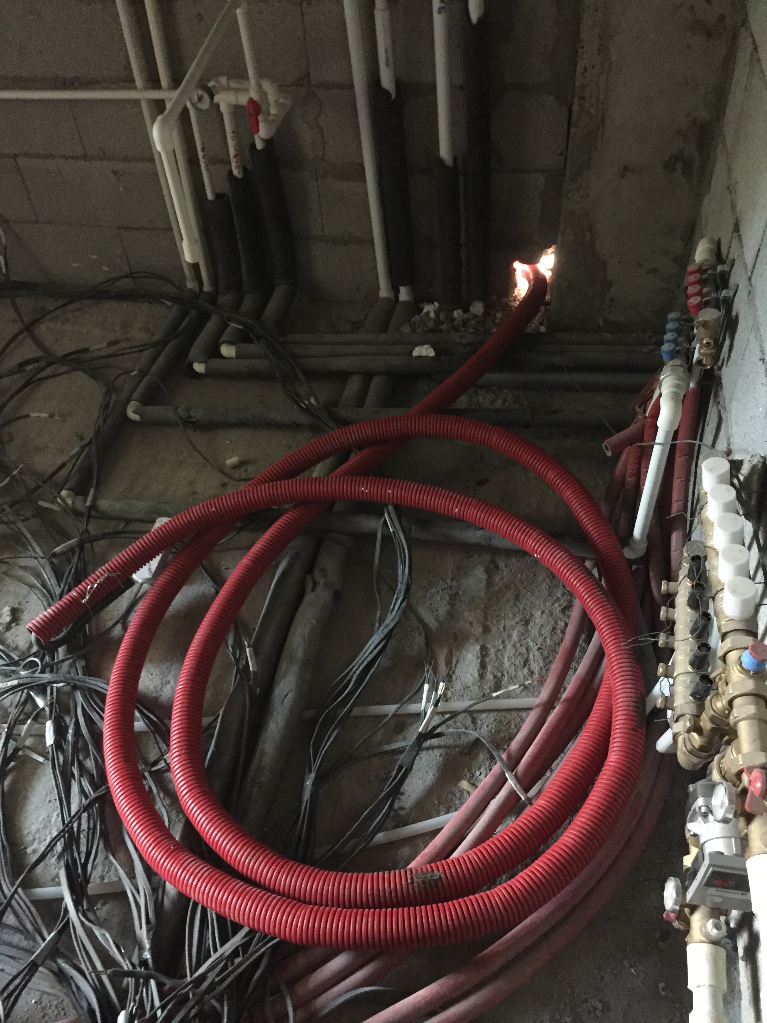
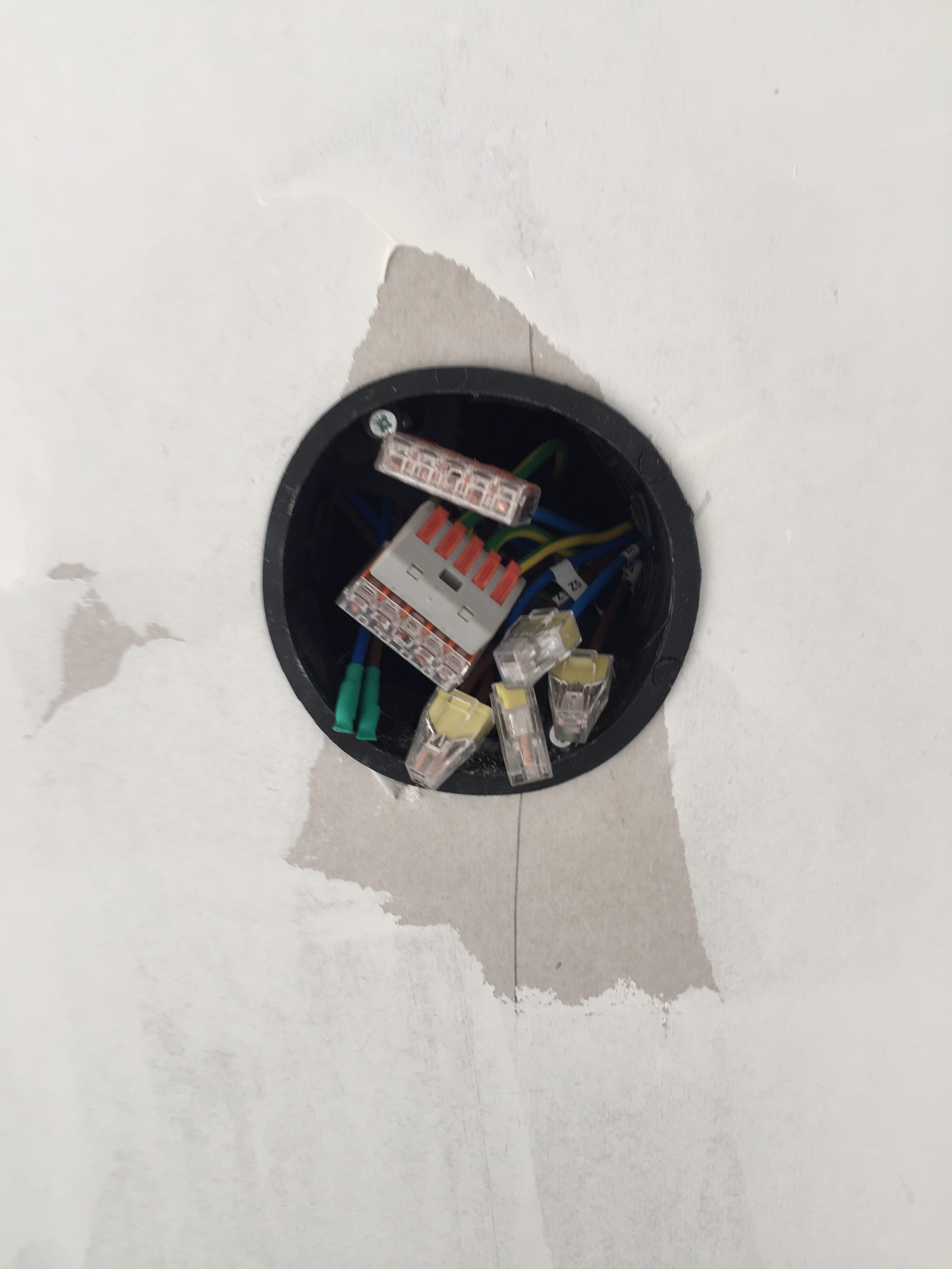
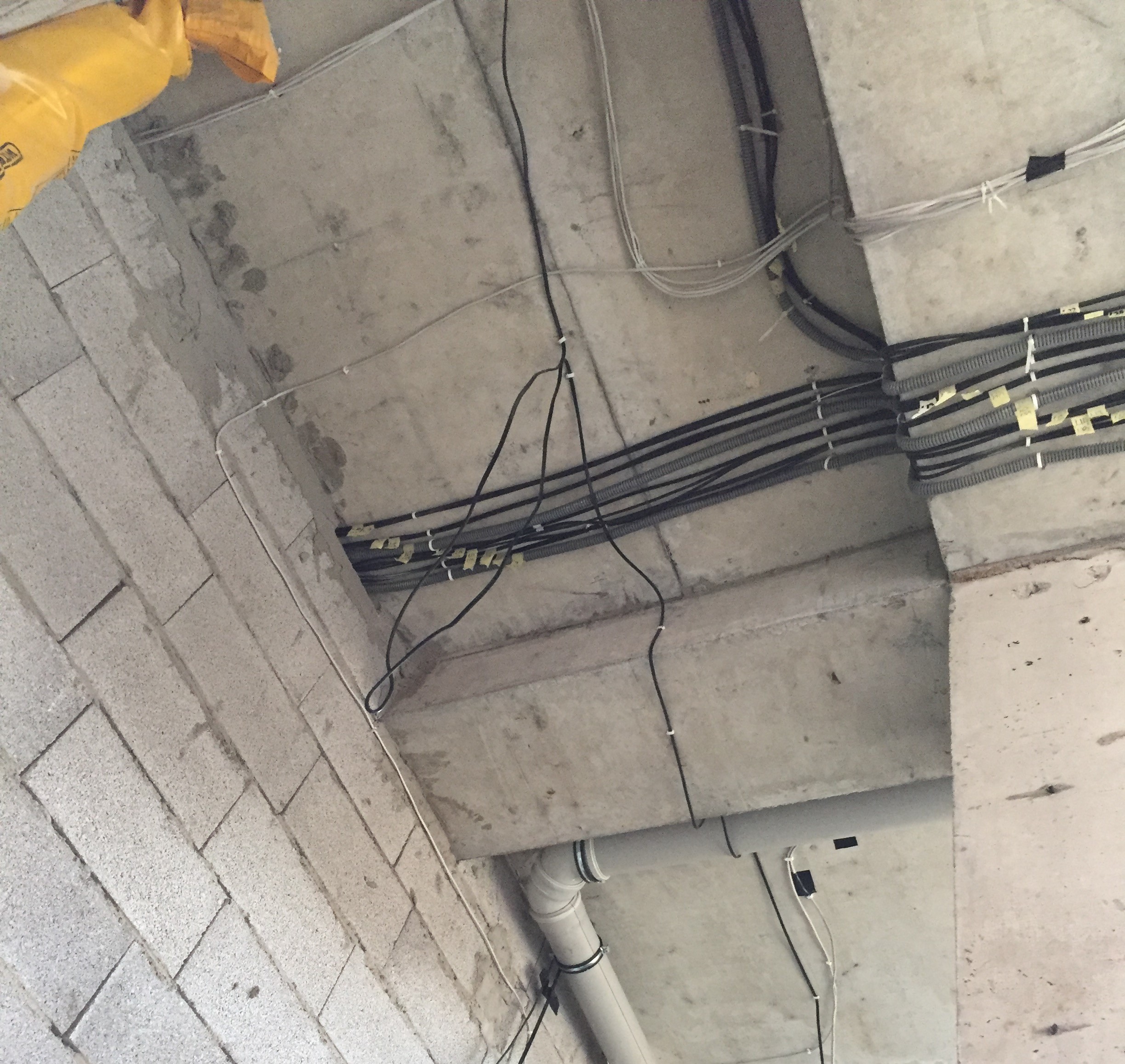
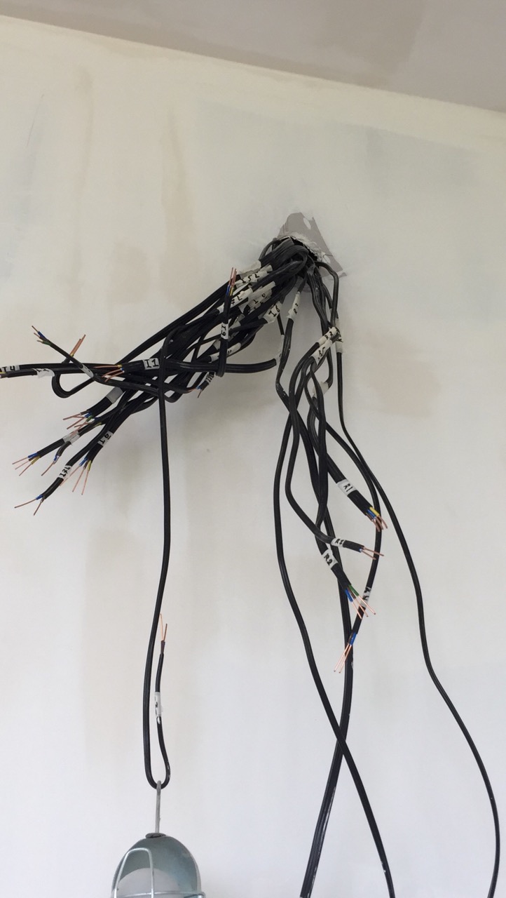
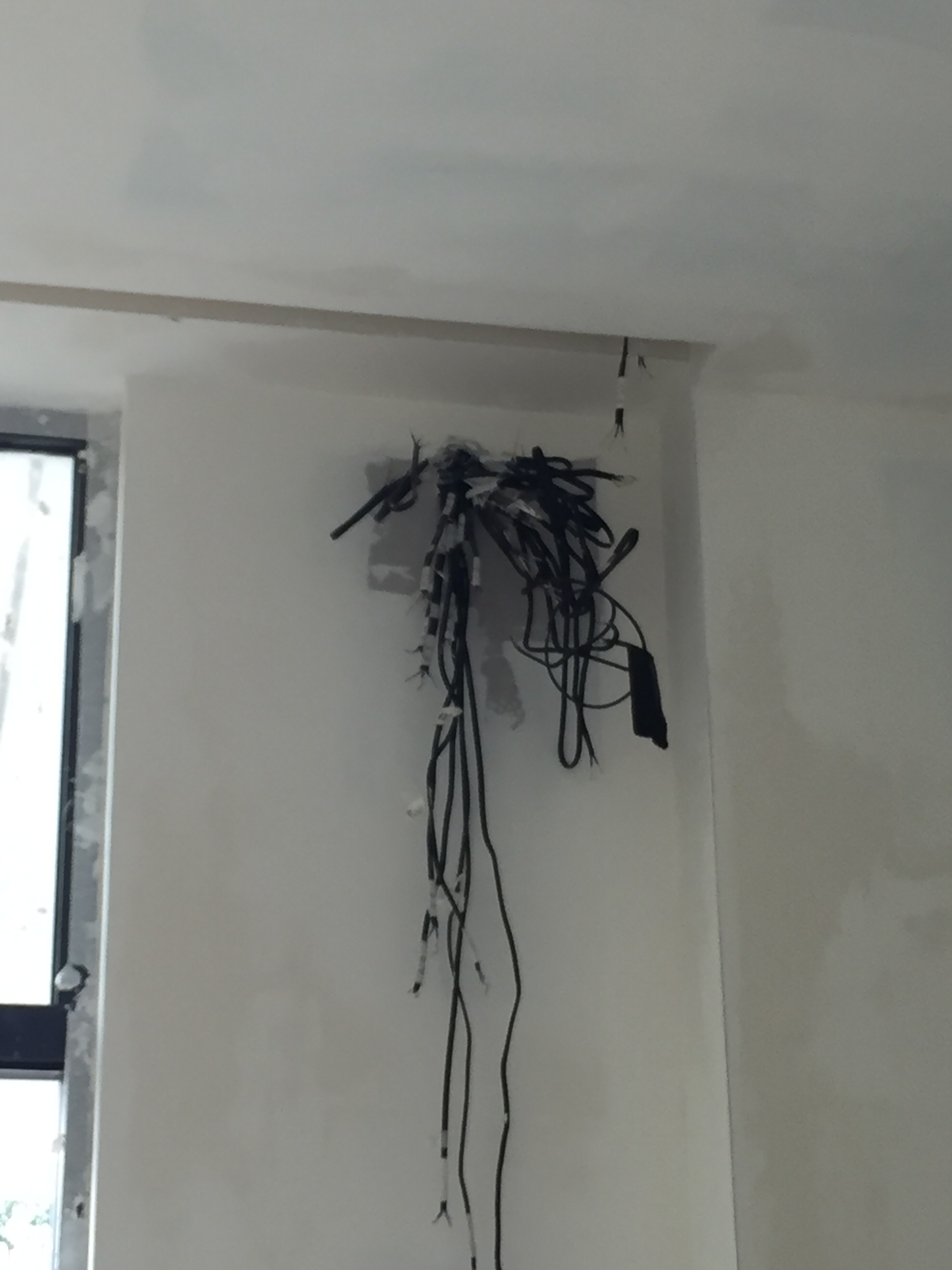
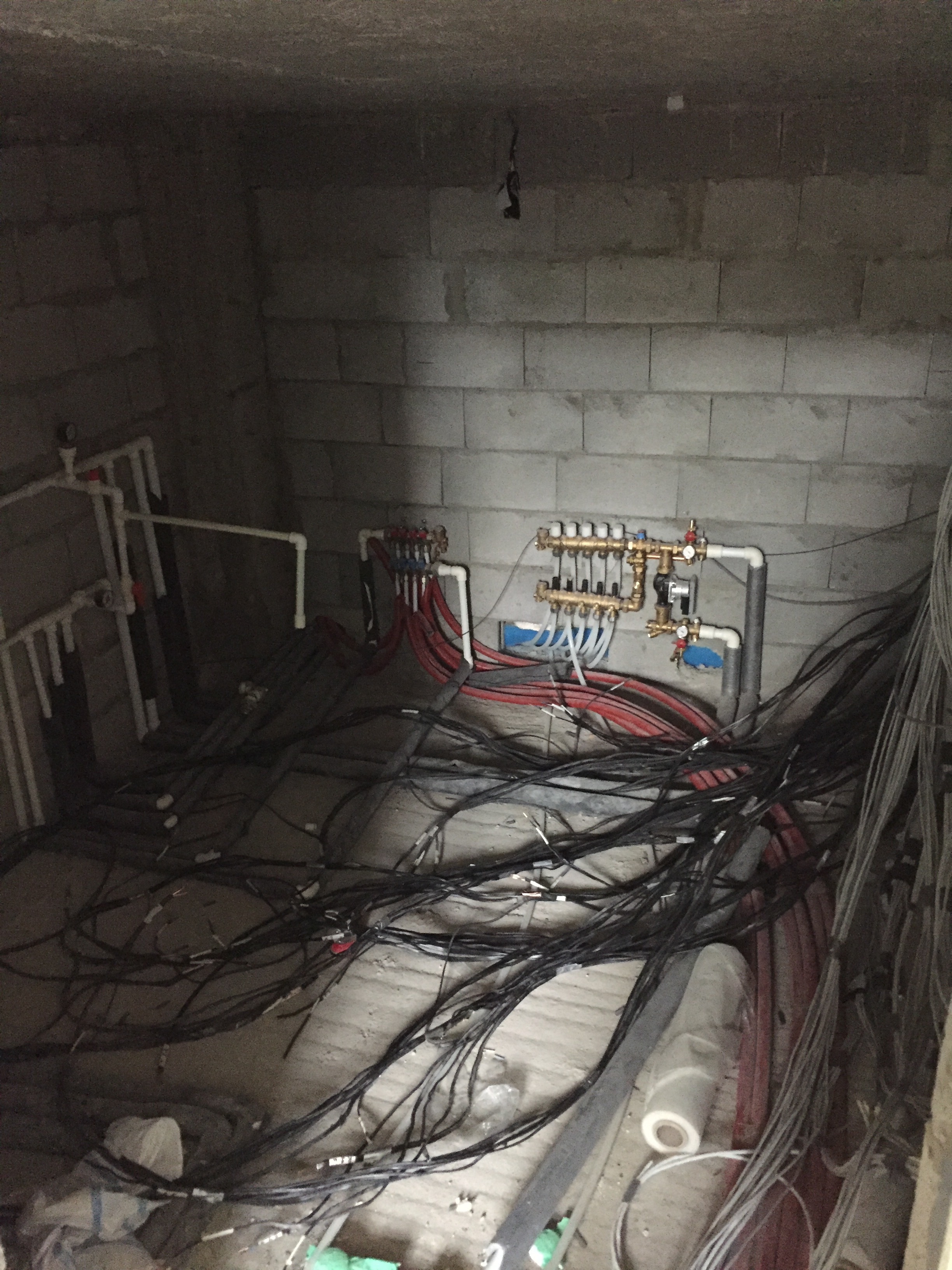
I ran all separate wires for each light source
I’ve also decided to run power cables together with CAT5E cables till the light switch. This power cables will not be used but they will be there in case I decide to change something (Plan B )
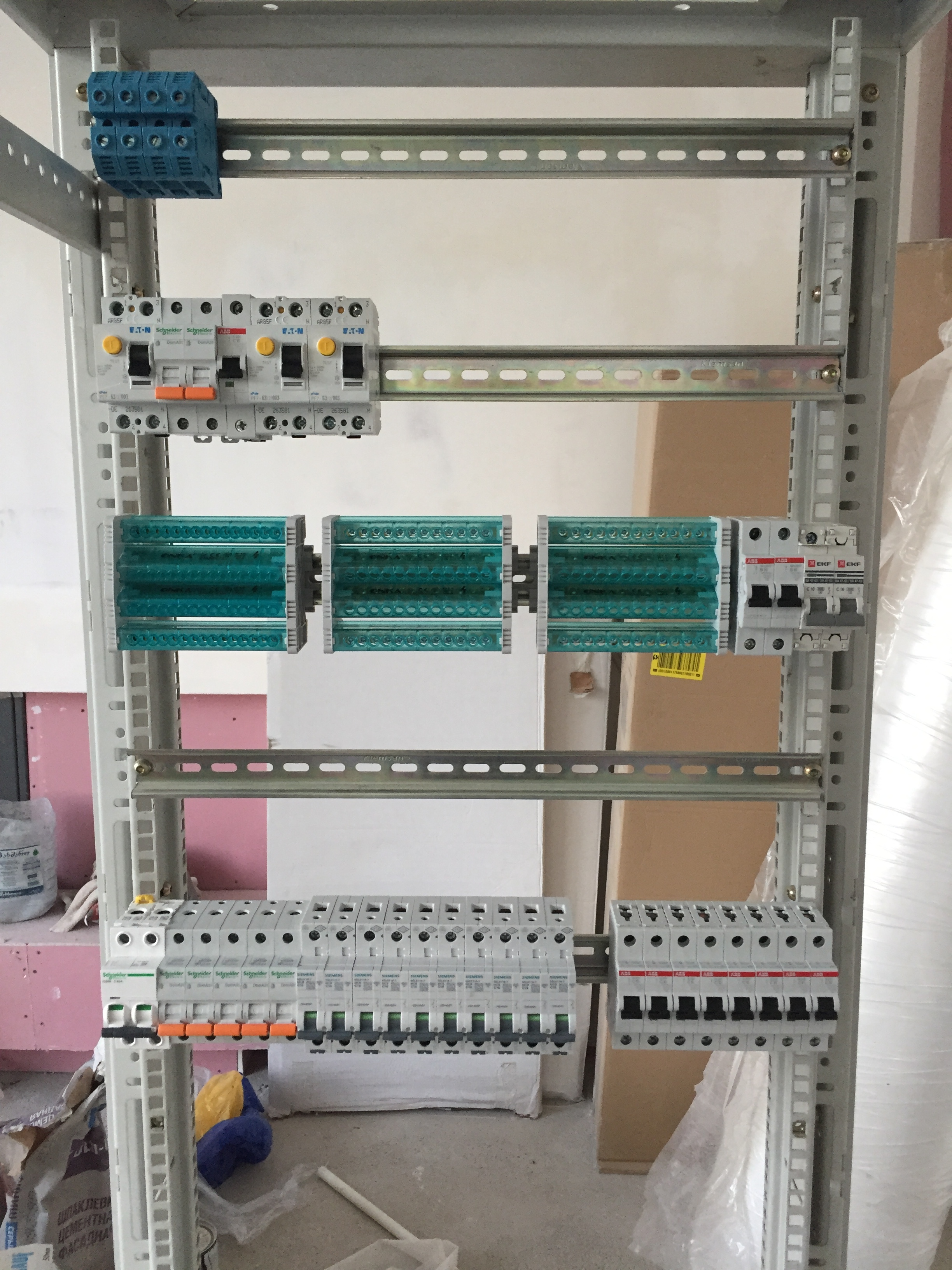
I’ve done all the wiring by myself as my country’s legislation is not as strict as in Australia. But I’m not confidant enough to build the main distribution panel by myself so I’m planning the electrician to do that. But as most electricians will do it the simplest way possible and the fact that I have non-standard wiring I first wanted to ask your advice. I can’t decide where to put relays (and which relays to get). As per my understanding safer way would be to add relays behind each breaker, but in that case I will need a lot of barkers which brings the cost up. Second option is to put the relays in front of the breaker which means that I will not need separate breaker for each light switch but this option is less secure because, in case of short circuit Relay might not handle the load and catch fire. This are all my thoughts, as I’m researching home automation only for 5-6 months now and have not yet practically done anything, I would like to hear your advice on this.
P.S. I will be posting updates and more details on my progress in this same topic
Welcome @HANNIBAL, and thanks for sharing your project!
I know it’s a lot of extra work and cost to run both UTP and mains cabling, but I think it’s a good insurance policy in case you want to change the setup later. One thing that nags me about my current setup is that there’s no mains wiring anywhere to light switches, so if I wanted to sell the house and rewire it in a more traditional way it would be a huge job. By putting in both sets of cables you’re covering yourself, whatever happens.
For the relays, the way I arranged it with my electrician was to have groups of relays behind circuit breakers in much the same way as a normal wiring pattern would be set up. For example, if you have 10A circuit breakers for lighting circuits, it’s normal in most homes to have multiple lighting circuits to keep the total load on each circuit breaker at a safe level. You might have one 10A breaker supplying power to one part of the house, and another 10A breaker supplying power to lights in another part of the house. The switching is normally done locally but the important thing is keeping the maximum theoretical load of everything on the circuit well below the rating of the breaker.
Mine is the same, but instead of each lighting circuit wandering off around part of the house, it goes to the inputs on the relays, which then go to the loads. Each group of relays is small enough that the total load if every single one of them was turned on is still well less than the rating on the breaker that supplies that group.
As a general principle, circuit breakers should always be as far up-stream as they can go, because they only protect what’s connected behind them.
Welcome to the wild world of DIY home automation. Ditto to what Jon said and I follow that with a question… What country are you in? Might help a lot as we follow you through this.
Thanks for your reply’s @jon and @Guru_Of_Nothing,
I’m in Georgia (Not the state, the country of Georgia ) Let me share some more data of my house.
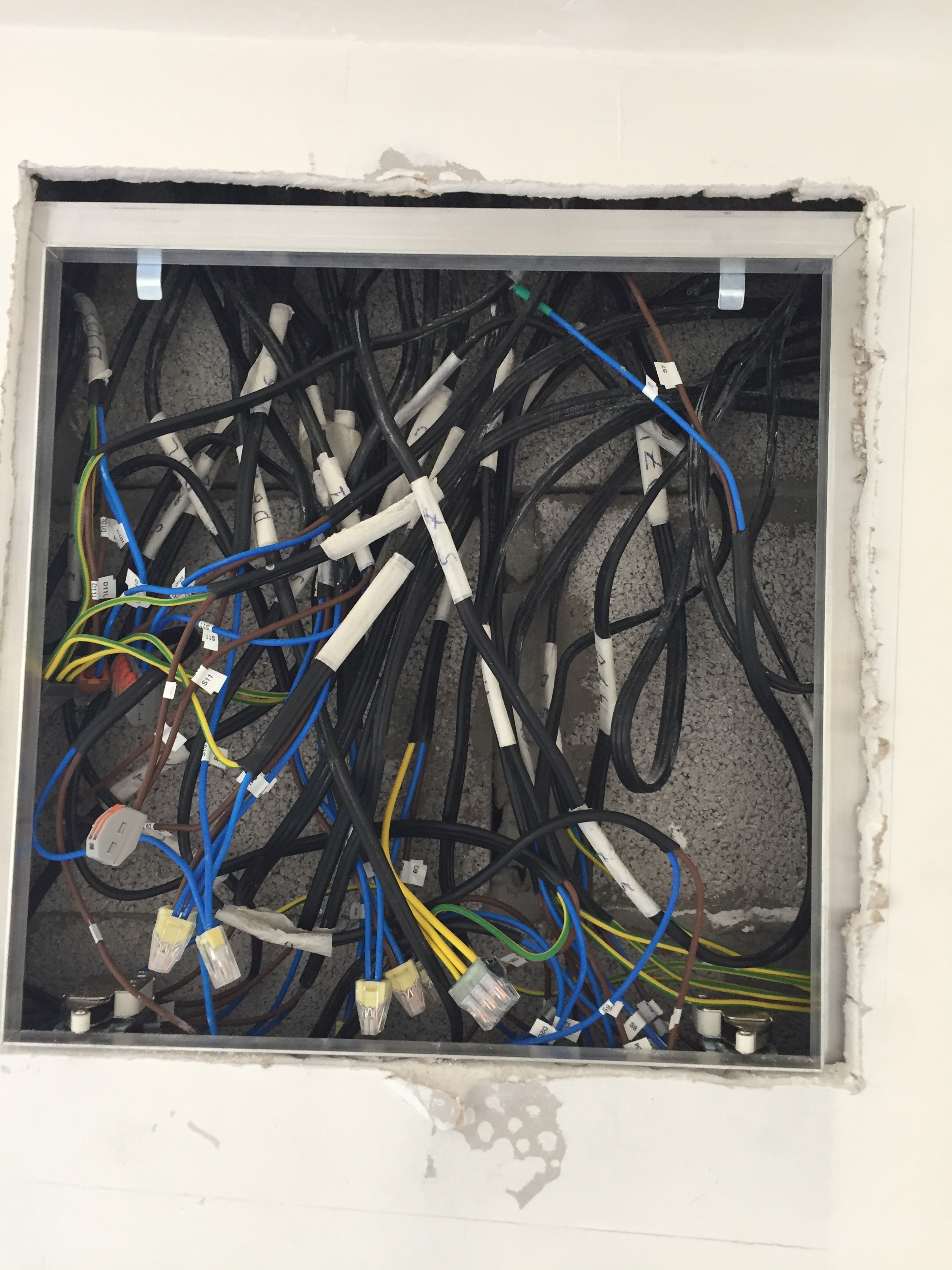
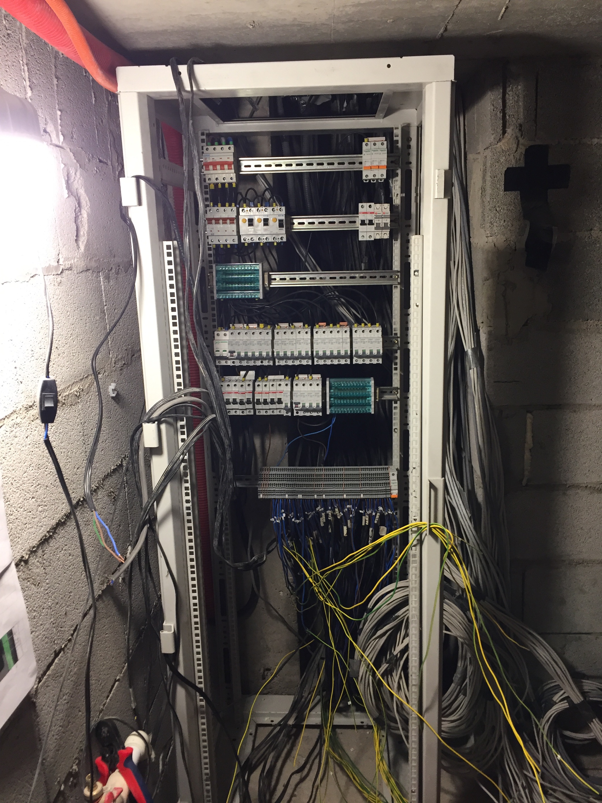
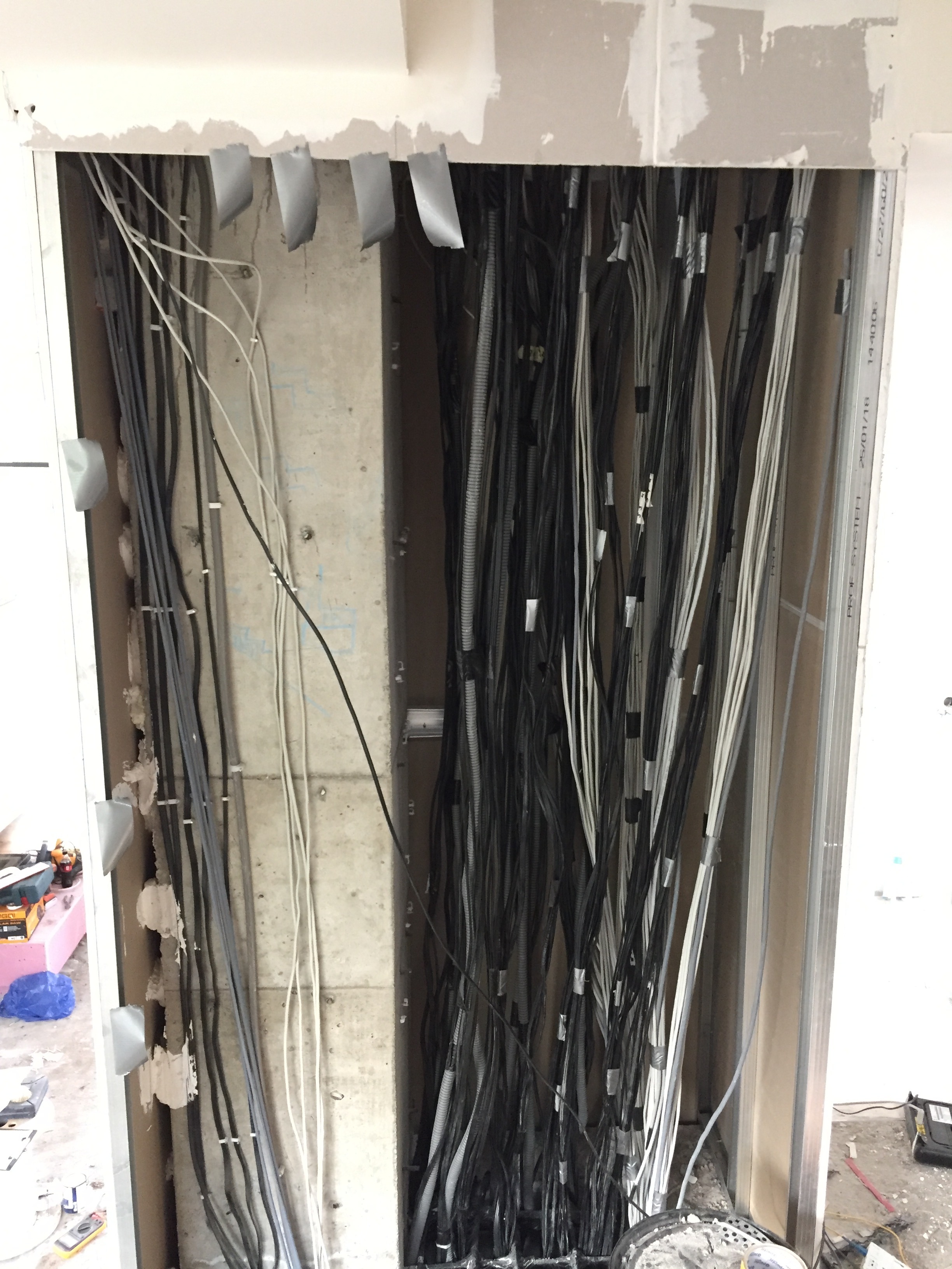
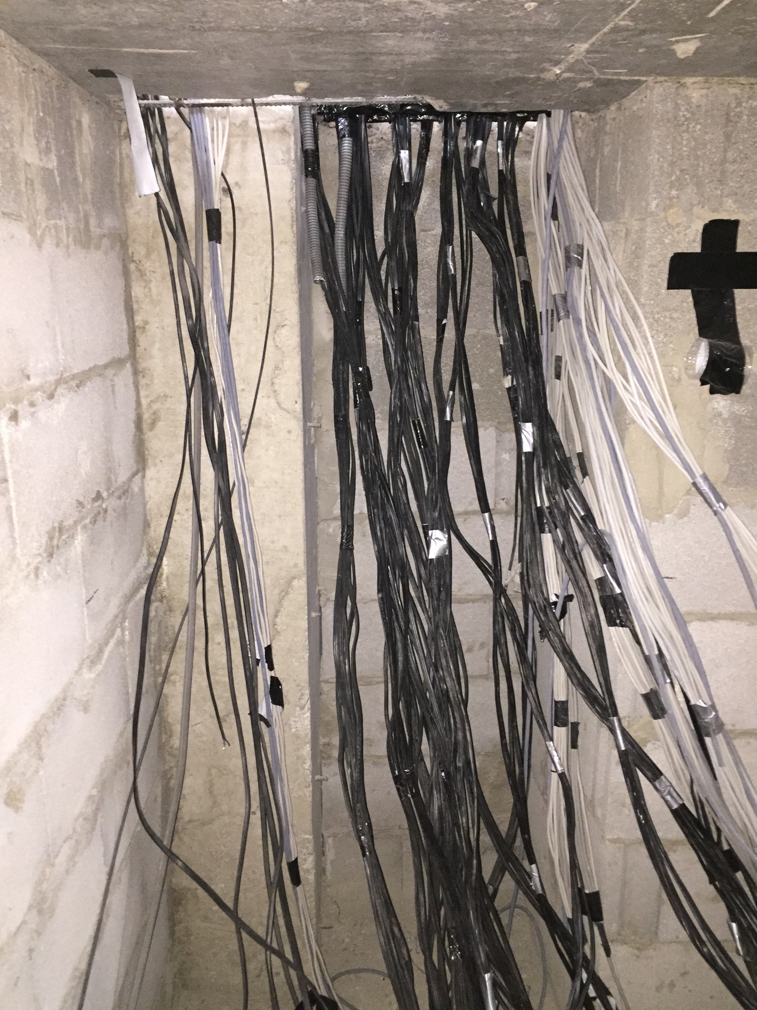
Number of wires going in to the distribution board:
Lighting: 71 wires
Sockets: 29 Wires
CAT5E STP: 65
CAT6 STP: 23 (4 for each TV and WiFi points)
My main questions are with relays as electricians in Georgia don’t quite understand what I actually need, I need to plan and execute that part by myself as well. I have 2 questions regarding that. 1) Will I need one relay to each wire? If yes it will be quite hard to fit 100 relays in distribution board. 2) I’m planning on adding several differential circuit breakers which are sensitive things and will move in force in case of 30mA current outflow, is there a chance that because of the relay in the middle it might not function correctly?
Thanks in advance for your reply’s and sorry if I’m asking boring questions
Awesome! I once worked with a guy who was born in Tbilisi. Says there is a lot of mountains around there.
As far as the basics of the electrical stuff goes, I can’t speak to exactly what is required for your electrical installation there since I am not an electrician there… or even here for that matter But the principals are the same. In pretty much any country with formal electrical practices, the circuit breaker needs to be as close to the source as possible, so basically where the power enters your home (usually). The control relays go in between the breaker and the load like the lights or outlets. So this means that if you want every light to have it’s own control, it has to have it’s own relay. That could mean that all 71 of your wires has a relay. That could mean that a number of them are fed by one circuit breaker depending on the rating of the breaker so that would be easier to house all the breakers in one panel but it still means that there will be a lot of relays. If you have multiple lights in a room that you want turned on and off together, then those can be fed by one relay, limiting the number of relays required. The CAT cable is terminated in a network patch panel and you can use RJ45 plugs to make the connections to those wires.
As to your question about whe4ther the breakers will function if behind a relay, the answer is yes. The breaker is looking for a total load to cause it to trip. It won’t care that there is a relay between it and the load as long as the combined loads being fed from it are less than it’s total rated capacity. As far as what those specifications are, I can’t say since I don’t know the details of your electrical systems there. The function is the same though. In my case, my house has a LOT of breakers.
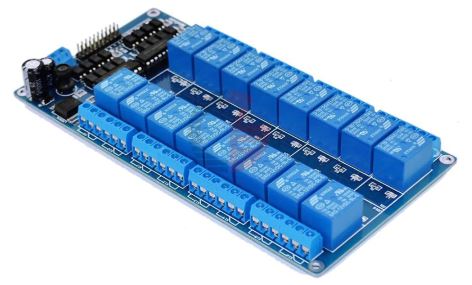
Now regarding the smart part. Again a question regarding relays Since I’m running out of budget, I’m planning to do the switching part using one of this relays:
Is it OK to do it with it and is there any particular model that you would recommend
if your looking at keeping a really clean setup, id recommend going with more traditional DIN Mounted relays and using a relay driver like the one Freetronics make their really nice and once you have your head around how they work with the I2C Bus its pretty cool.
Im yet to see any DIN Mount brackets for them im actually working on one right now that i plan to post here hopefully in the next few days, but im also working on a DIN mount for the EtherTen too.
if budget is really tight and you cant afford going that way then something like a 16 Channel Relay board is a good starting point. just make sure when your putting it all together there cant be a chance for any of your cable to fall out of the arduino. possibly by using a prototyping shield to make a adapter board to something like a 16way IDC connector.
Either way, i love what your doing and look forward to seeing your future updates
As already mentioned by Bedrock , i would recommend using din mounted relays ,and use a driver board…Looking forward to more pics of your build .
Cheers
Frank
As this is my first project with home automation and have no practice on actually making one, I thought it’s a good idea to build something like test system using 16 Channel Relay board. Also I need to check the CAT5e wires which I ran to each light switch, those where cheapo cables which are not 100% copper and I’m concerned about voltage drop which might occur and make the system malfunction since some wires are 20-25 meters long.
I really enjoy coming back here as there is always someone willing to help out and I hope that my progress will help others as well.
Thanks
How are you doing your light switches? sorta like how Jon did his?
depending on what sorta voltage drop you get if your using his design, it might not be as bad as you think. jons using if i recall correctly 4K7 resistor, this drop that 12v down to roughly 3.3v.
so if your voltage is lower then 12v because of cable drop you could always put a lower value resistor to get the same effect
id suggest getting one of the DIN mount relays to test with, i have a working system using a Etherten and 4 Relay8 boards
heres a link to my other topic that covers the code behind this
I’ve actually got 4-Channel Relay Driver Module and EtherMega. As per my understanding this 4 channel module doesn’t use I2C and will be used just to provide needed power for the relays.
Starting to come along, its looking good tho, my switchboards arrived in the warehouse today so hopefully in the next week or 2 i can start to get mine in,
 )
)

 But the principals are the same. In pretty much any country with formal electrical practices, the circuit breaker needs to be as close to the source as possible, so basically where the power enters your home (usually). The control relays go in between the breaker and the load like the lights or outlets. So this means that if you want every light to have it’s own control, it has to have it’s own relay. That could mean that all 71 of your wires has a relay. That could mean that a number of them are fed by one circuit breaker depending on the rating of the breaker so that would be easier to house all the breakers in one panel but it still means that there will be a lot of relays. If you have multiple lights in a room that you want turned on and off together, then those can be fed by one relay, limiting the number of relays required. The CAT cable is terminated in a network patch panel and you can use RJ45 plugs to make the connections to those wires.